US9806873B2 - Method and apparatus for controlling discontinuous reception in mobile communication system - Google Patents
Method and apparatus for controlling discontinuous reception in mobile communication system Download PDFInfo
- Publication number
- US9806873B2 US9806873B2 US14/397,007 US201214397007A US9806873B2 US 9806873 B2 US9806873 B2 US 9806873B2 US 201214397007 A US201214397007 A US 201214397007A US 9806873 B2 US9806873 B2 US 9806873B2
- Authority
- US
- United States
- Prior art keywords
- drx cycle
- drx
- received
- short drx
- short
- Prior art date
- Legal status (The legal status is an assumption and is not a legal conclusion. Google has not performed a legal analysis and makes no representation as to the accuracy of the status listed.)
- Active, expires
Links
- 238000000034 method Methods 0.000 title claims abstract description 46
- 238000010295 mobile communication Methods 0.000 title claims abstract description 17
- 230000005540 biological transmission Effects 0.000 claims description 115
- 230000008569 process Effects 0.000 description 26
- 238000012546 transfer Methods 0.000 description 22
- 239000000969 carrier Substances 0.000 description 10
- 230000002776 aggregation Effects 0.000 description 9
- 238000004220 aggregation Methods 0.000 description 9
- 230000008859 change Effects 0.000 description 9
- 230000011664 signaling Effects 0.000 description 9
- 238000009482 thermal adhesion granulation Methods 0.000 description 7
- 238000004891 communication Methods 0.000 description 5
- 230000006870 function Effects 0.000 description 5
- 238000010586 diagram Methods 0.000 description 4
- 238000005516 engineering process Methods 0.000 description 4
- 230000004913 activation Effects 0.000 description 3
- 230000009849 deactivation Effects 0.000 description 3
- 238000012545 processing Methods 0.000 description 3
- 238000011161 development Methods 0.000 description 2
- 230000007257 malfunction Effects 0.000 description 2
- 238000007726 management method Methods 0.000 description 2
- 238000013507 mapping Methods 0.000 description 2
- 238000012544 monitoring process Methods 0.000 description 2
- XHSQDZXAVJRBMX-UHFFFAOYSA-N 2-(5,6-dichlorobenzimidazol-1-yl)-5-(hydroxymethyl)oxolane-3,4-diol Chemical compound OC1C(O)C(CO)OC1N1C2=CC(Cl)=C(Cl)C=C2N=C1 XHSQDZXAVJRBMX-UHFFFAOYSA-N 0.000 description 1
- 208000008469 Peptic Ulcer Diseases 0.000 description 1
- 230000003044 adaptive effect Effects 0.000 description 1
- 230000004931 aggregating effect Effects 0.000 description 1
- 230000008901 benefit Effects 0.000 description 1
- 230000007423 decrease Effects 0.000 description 1
- 230000000694 effects Effects 0.000 description 1
- 230000002708 enhancing effect Effects 0.000 description 1
- 230000010354 integration Effects 0.000 description 1
- 230000007774 longterm Effects 0.000 description 1
- 238000012423 maintenance Methods 0.000 description 1
- 238000012986 modification Methods 0.000 description 1
- 230000004048 modification Effects 0.000 description 1
- 230000009467 reduction Effects 0.000 description 1
- 230000007704 transition Effects 0.000 description 1
Images


Classifications
-
- H—ELECTRICITY
- H04—ELECTRIC COMMUNICATION TECHNIQUE
- H04L—TRANSMISSION OF DIGITAL INFORMATION, e.g. TELEGRAPHIC COMMUNICATION
- H04L5/00—Arrangements affording multiple use of the transmission path
- H04L5/0091—Signaling for the administration of the divided path
- H04L5/0096—Indication of changes in allocation
- H04L5/0098—Signalling of the activation or deactivation of component carriers, subcarriers or frequency bands
-
- H—ELECTRICITY
- H04—ELECTRIC COMMUNICATION TECHNIQUE
- H04J—MULTIPLEX COMMUNICATION
- H04J11/00—Orthogonal multiplex systems, e.g. using WALSH codes
- H04J11/0069—Cell search, i.e. determining cell identity [cell-ID]
-
- H—ELECTRICITY
- H04—ELECTRIC COMMUNICATION TECHNIQUE
- H04W—WIRELESS COMMUNICATION NETWORKS
- H04W4/00—Services specially adapted for wireless communication networks; Facilities therefor
- H04W4/18—Information format or content conversion, e.g. adaptation by the network of the transmitted or received information for the purpose of wireless delivery to users or terminals
-
- H—ELECTRICITY
- H04—ELECTRIC COMMUNICATION TECHNIQUE
- H04L—TRANSMISSION OF DIGITAL INFORMATION, e.g. TELEGRAPHIC COMMUNICATION
- H04L5/00—Arrangements affording multiple use of the transmission path
- H04L5/003—Arrangements for allocating sub-channels of the transmission path
- H04L5/0032—Distributed allocation, i.e. involving a plurality of allocating devices, each making partial allocation
-
- H—ELECTRICITY
- H04—ELECTRIC COMMUNICATION TECHNIQUE
- H04W—WIRELESS COMMUNICATION NETWORKS
- H04W24/00—Supervisory, monitoring or testing arrangements
- H04W24/02—Arrangements for optimising operational condition
-
- H—ELECTRICITY
- H04—ELECTRIC COMMUNICATION TECHNIQUE
- H04W—WIRELESS COMMUNICATION NETWORKS
- H04W24/00—Supervisory, monitoring or testing arrangements
- H04W24/10—Scheduling measurement reports ; Arrangements for measurement reports
-
- H—ELECTRICITY
- H04—ELECTRIC COMMUNICATION TECHNIQUE
- H04W—WIRELESS COMMUNICATION NETWORKS
- H04W48/00—Access restriction; Network selection; Access point selection
- H04W48/16—Discovering, processing access restriction or access information
-
- H—ELECTRICITY
- H04—ELECTRIC COMMUNICATION TECHNIQUE
- H04W—WIRELESS COMMUNICATION NETWORKS
- H04W52/00—Power management, e.g. TPC [Transmission Power Control], power saving or power classes
- H04W52/02—Power saving arrangements
- H04W52/0209—Power saving arrangements in terminal devices
- H04W52/0212—Power saving arrangements in terminal devices managed by the network, e.g. network or access point is master and terminal is slave
- H04W52/0216—Power saving arrangements in terminal devices managed by the network, e.g. network or access point is master and terminal is slave using a pre-established activity schedule, e.g. traffic indication frame
-
- H—ELECTRICITY
- H04—ELECTRIC COMMUNICATION TECHNIQUE
- H04W—WIRELESS COMMUNICATION NETWORKS
- H04W52/00—Power management, e.g. TPC [Transmission Power Control], power saving or power classes
- H04W52/02—Power saving arrangements
- H04W52/0209—Power saving arrangements in terminal devices
- H04W52/0225—Power saving arrangements in terminal devices using monitoring of external events, e.g. the presence of a signal
- H04W52/0241—Power saving arrangements in terminal devices using monitoring of external events, e.g. the presence of a signal where no transmission is received, e.g. out of range of the transmitter
-
- H—ELECTRICITY
- H04—ELECTRIC COMMUNICATION TECHNIQUE
- H04W—WIRELESS COMMUNICATION NETWORKS
- H04W56/00—Synchronisation arrangements
- H04W56/0005—Synchronisation arrangements synchronizing of arrival of multiple uplinks
-
- H—ELECTRICITY
- H04—ELECTRIC COMMUNICATION TECHNIQUE
- H04W—WIRELESS COMMUNICATION NETWORKS
- H04W56/00—Synchronisation arrangements
- H04W56/004—Synchronisation arrangements compensating for timing error of reception due to propagation delay
- H04W56/0045—Synchronisation arrangements compensating for timing error of reception due to propagation delay compensating for timing error by altering transmission time
-
- H04W72/042—
-
- H04W72/0426—
-
- H—ELECTRICITY
- H04—ELECTRIC COMMUNICATION TECHNIQUE
- H04W—WIRELESS COMMUNICATION NETWORKS
- H04W72/00—Local resource management
- H04W72/04—Wireless resource allocation
- H04W72/044—Wireless resource allocation based on the type of the allocated resource
- H04W72/0453—Resources in frequency domain, e.g. a carrier in FDMA
-
- H—ELECTRICITY
- H04—ELECTRIC COMMUNICATION TECHNIQUE
- H04W—WIRELESS COMMUNICATION NETWORKS
- H04W72/00—Local resource management
- H04W72/20—Control channels or signalling for resource management
- H04W72/23—Control channels or signalling for resource management in the downlink direction of a wireless link, i.e. towards a terminal
-
- H—ELECTRICITY
- H04—ELECTRIC COMMUNICATION TECHNIQUE
- H04W—WIRELESS COMMUNICATION NETWORKS
- H04W72/00—Local resource management
- H04W72/20—Control channels or signalling for resource management
- H04W72/27—Control channels or signalling for resource management between access points
-
- H04W76/022—
-
- H04W76/025—
-
- H04W76/048—
-
- H—ELECTRICITY
- H04—ELECTRIC COMMUNICATION TECHNIQUE
- H04W—WIRELESS COMMUNICATION NETWORKS
- H04W76/00—Connection management
- H04W76/10—Connection setup
- H04W76/12—Setup of transport tunnels
-
- H—ELECTRICITY
- H04—ELECTRIC COMMUNICATION TECHNIQUE
- H04W—WIRELESS COMMUNICATION NETWORKS
- H04W76/00—Connection management
- H04W76/10—Connection setup
- H04W76/15—Setup of multiple wireless link connections
-
- H—ELECTRICITY
- H04—ELECTRIC COMMUNICATION TECHNIQUE
- H04W—WIRELESS COMMUNICATION NETWORKS
- H04W76/00—Connection management
- H04W76/20—Manipulation of established connections
- H04W76/28—Discontinuous transmission [DTX]; Discontinuous reception [DRX]
-
- H—ELECTRICITY
- H04—ELECTRIC COMMUNICATION TECHNIQUE
- H04W—WIRELESS COMMUNICATION NETWORKS
- H04W76/00—Connection management
- H04W76/30—Connection release
- H04W76/34—Selective release of ongoing connections
-
- H—ELECTRICITY
- H04—ELECTRIC COMMUNICATION TECHNIQUE
- H04W—WIRELESS COMMUNICATION NETWORKS
- H04W74/00—Wireless channel access, e.g. scheduled or random access
- H04W74/08—Non-scheduled or contention based access, e.g. random access, ALOHA, CSMA [Carrier Sense Multiple Access]
- H04W74/0833—Non-scheduled or contention based access, e.g. random access, ALOHA, CSMA [Carrier Sense Multiple Access] using a random access procedure
-
- Y02B60/50—
-
- Y—GENERAL TAGGING OF NEW TECHNOLOGICAL DEVELOPMENTS; GENERAL TAGGING OF CROSS-SECTIONAL TECHNOLOGIES SPANNING OVER SEVERAL SECTIONS OF THE IPC; TECHNICAL SUBJECTS COVERED BY FORMER USPC CROSS-REFERENCE ART COLLECTIONS [XRACs] AND DIGESTS
- Y02—TECHNOLOGIES OR APPLICATIONS FOR MITIGATION OR ADAPTATION AGAINST CLIMATE CHANGE
- Y02D—CLIMATE CHANGE MITIGATION TECHNOLOGIES IN INFORMATION AND COMMUNICATION TECHNOLOGIES [ICT], I.E. INFORMATION AND COMMUNICATION TECHNOLOGIES AIMING AT THE REDUCTION OF THEIR OWN ENERGY USE
- Y02D30/00—Reducing energy consumption in communication networks
- Y02D30/70—Reducing energy consumption in communication networks in wireless communication networks
Definitions
- the present invention relates to a method and apparatus for performing discontinuous reception (DRX) in a mobile communication system.
- DRX discontinuous reception
- Mobile communication systems have been developed to provide communication services to users while they are moving. With the rapid development of communication technology, mobile communication systems have provided rapid data communication services as well as voice communication services.
- LTE Long Term Evolution
- 3GPP 3 rd Generation Partnership Project
- LTE mobile communication systems have employed discontinuous reception (DRX), so that UE devices transmit reverse-control signals only during the Active Time of a DRX cycle, thereby minimizing their power consumption.
- DRX discontinuous reception
- New definition for operations of UE devices is required for their maximum process performance during the DRX.
- the present invention has been made in view of the above problems, and provides a method and apparatus for defining operations of user equipment (UE) devices in a situation forcing to increase beyond the process performance during the discontinuous reception (DRX) to reduce the power consumption, the complexity, and the costs of UE devices.
- UE user equipment
- the present invention provides a method for controlling Discontinuous Reception (DRX) of a user equipment (UE) device in a mobile communication system, including: receiving DRX-configuration information from an Evolved Node B (ENB); determining whether a first condition is satisfied, the first condition determining whether a current sub-frame exists between a first time point that the DRX-configuration information is received and a second time point that an event for triggering the application of a short DRX cycle occurs; and applying, when a first condition is satisfied, a preset DRX cycle to the system.
- Evolved Node B ENB
- the present invention provides a user equipment (UE) device for controlling Discontinuous Reception (DRX) in a mobile communication system, including: a transceiver for receiving DRX-configuration information from an Evolved Node B (ENB); and a controller for: determining whether a first condition is satisfied, the first condition determining whether a current sub-frame exists between a first time point that the DRX-configuration information is received and a second time point that an event for triggering the application of a short DRX cycle occurs; and applying, when a first condition is satisfied, a preset DRX cycle to the system.
- UE user equipment
- the present invention can keep UE related to DRX at a proper level of process performance, thereby reducing the power consumption and the costs.
- FIG. 1 illustrates a view of the configuration of an LTE system according to an embodiment of the present invention
- FIG. 2 illustrates a view of the wireless protocol stack of an LTE system according to an embodiment of the present invention
- FIG. 3 illustrates a view that describes a general DRX cycle
- FIG. 4 illustrates a flow chart that describes operations of a UE device when a short DRX cycle is applied to active data transmission and reception, according to a first embodiment of the present invention
- FIG. 5 illustrates a flow chart that describes a first example where operations of a UE device when an abrupt onDuration is created, according to a first embodiment of the present invention
- FIG. 6 illustrates a flow chart that describes a second example where operations of a UE device when an abrupt onDuration is created, according to a first embodiment of the present invention
- FIG. 7 illustrates a flow chart that describes a third example where operations of a UE device when an abrupt onDuration is created, according to a first embodiment of the present invention
- FIG. 8 illustrates a view that describes formats of PDCP PDU
- FIG. 9 illustrates a flow chart that describes the entire operation of a second embodiment of the present invention.
- FIG. 10 illustrates a view that describes local transfer of data in the system
- FIG. 11 illustrates a view that describes operations of a UE device according to a second embodiment of the present invention
- FIG. 12 illustrates a view that describes carrier integration
- FIG. 13 illustrates a flow chart that describes operations of a UE device when it configures TAG, according to a third embodiment of the present invention
- FIG. 14 illustrates a flow chart that describes operations of a UE device when reverse transmission is performed in two sub-frames adjacent to different TAG serving cells, a according to a third embodiment of the present invention
- FIG. 15 illustrates a view that describes a problem where the boundaries of reverse sub-frames between two serving-cells are not bordered each other;
- FIG. 16 illustrates a schematic block diagram of a UE device according to an embodiment of the invention.
- FIG. 17 illustrates a schematic block diagram of an ENB according to an embodiment of the invention.
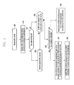
- FIG. 1 illustrates a view of the configuration of an LTE system according to an embodiment of the invention.
- the LTE system configures the wireless access network, including Evolved Node Bs (ENBs) 105 , 110 , 115 , and 120 , a mobility management entity (MME) 125 , and a serving-gateway (S-GW) 130 .
- EMBs Evolved Node Bs
- MME mobility management entity
- S-GW serving-gateway
- UE 135 is connected to an external network via the ENB 105 , 110 , 115 , or 120 and the S-GW 130 .
- ENBs 105 to 120 correspond to conventional Node B of the UMTS system.
- ENBs 105 to 120 are connected to UE 135 via wireless channels, performing more complicated functions than conventional Node B. Since real-time Voice over IP (VoIP) services and all user traffics are served via shared channels in LTE system, devices are required to collect information regarding states, such as buffer states of UE, available transmission power states, channel states, etc., and to make a schedule. This job can be performed via ENBs 105 to 120 .
- One ENB can control a number of cells. For example, in order to implement a transmission rate of 100 Mbps, LTE system employs orthogonal frequency division multiplexing (OFDM) at a bandwidth of 20 MHz.
- OFDM orthogonal frequency division multiplexing
- S-GW 130 is a device that establishes data bearers. S-GW 130 can create or remove data bearers according to the control of MME 125 .
- MME 125 manages the mobility of UE and controls a variety of functions. MME 125 connects to a number of ENBs.
- FIG. 2 illustrates a view of the wireless protocol stack of an LTE system according to an embodiment of the invention.
- UE and ENB have packet data convergence protocols (PDCP) 205 and 240 , radio link control (RLC) 210 and 235 , and medium access controls (MAC) 215 and 230 , respectively.
- PDCP 205 and 240 compress/decompress IP header.
- RLC 210 and 235 reconfigure PDCP packet data unit (PDU) in proper size and perform an ARQ operation.
- MAC 215 and 230 connect to a number of RLC layer devices configured in one UE device.
- MAC 215 and 230 multiplex RLC PUDs to MAC PDU, and de-multiplex RLC PDUs from MAC PDU.
- PHY 220 and 225 in UE and ENB channel-code and modulate data from the upper layers, create OFDM symbols, and transmit them via a wireless channel.
- PHY 220 and 225 demodulate and channel-decode OFDM symbols transmitted via a wireless channel, and transfer them to the upper layers.
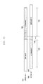
- FIG. 3 illustrates a view that describes a general DRX cycle.
- Discontinuous Reception is a method that monitors a forward scheduling channel (Physical Downlink Control Channel (PDCCH)), only for a period of time, i.e., an active time, and transmits a reverse direction signal related to channel quality (Channel Status Indicator/Information (CSI) and Sounding Reference Signal (SRS)), thereby minimizing power consumption in the UE for non-active time.
- a forward scheduling channel Physical Downlink Control Channel (PDCCH)
- CSI Channel Status Indicator/Information
- SRS Sounding Reference Signal
- Active time repeats at a DRX cycle.
- the application of Active time to UE varies depending on the traffic. For example, when UE meets a preset condition, it employs a relatively short period of time, i.e., a short DRX cycle 305 (or 1 st cycle). On the contrary, when UE doesn't meet the condition, it employs a long DRX cycle 310 (or 2 nd cycle).
- a timer for a relatively short period of active time i.e., on duration 315, onDuration
- an inactivity timer inactivityTimer
- the inactivityTimer is driven or re-driven each time new data is scheduled, and also extends a period of active time when the traffic of UE increases.
- CSI refers to feedback related to MIMO operations or the forward channel quality, such as Chanel Quality Indicator (CQI), Rank Indicator (RI), etc., and is transmitted via Physical Uplink Control Channel (PUCCH) or Physical Uplink Shared Channel (PUSCH).
- UE can be set to transmit CSI via a PUCCH transmission resource at a period of time.
- CSI on PUCCH When UE transmits CSI via the instructed PUCCH transmission resource, this is expressed as ‘CSI on PUCCH.’ If a sub-frame for CSI on PUCCH is scheduled to be transmitted via PUSCH (which is a reverse direction channel for transmission of MAC PDU of user data), UE transmits CSI by using part of the PUSCH transmission resource in order to comply with a single carrier transmission protocol, which is expressed as ‘CSI on PUSCH.’
- the transmission/reception of data may be performed in not a short DRX cycle but a long DRX cycle.
- This problem is caused because a short DRX cycle starts by the expiration of the inactivity timer; however the inactivity timer continues re-starting during the transmission/reception of data, so that it doesn't expire.
- the present invention is implemented to re-define the use condition of a short DRX cycle so that a short DRX cycle can be applied to the data transmission/reception even though an inactivity timer is operated. Meanwhile, the application of a long DRX cycle during the transmission/reception of data causes the following problems.
- FIG. 4 illustrates a flow chart that describes operations of UE according to a first embodiment of the present invention.
- UE receives DRX configuration information from ENB at a time point at step 405 .
- DRX configuration information includes a duration (length) of a short DRX cycle, duration (length) of a long DRX cycle, information for computing the start point of DRX, information regarding a duration (length) of on-duration (onDuration), and information regarding the expiration of an inactivity timer (inactivityTimer).
- RRC of UE receives the DRX configuration information and transfers it to the MAC controller.
- the MAC controller performs DRX operations by using the control information, as follows.
- UE determines whether meets to Condition 1 as follows before new subframes start, at step 410 . When UE meets Condition 1 , it proceeds with step 415 . On the contrary, when UE doesn't meet Condition 1 , it proceeds with step 420 .
- a current subframe is between t 1 and t 2 .
- Condition 1 is a condition to determine type of DRX cycle to be applied after UE has received DRX configuration information before UE performs DRX.
- UE For subframes meeting Condition 1 , i.e., from after DRX operation starts until an application condition of a short DRX cycle is met, UE employs a pre-defined DRX cycle. Since data transmission/reception has been less activated before an application condition of a short DRX cycle is established, the type of pre-defined DRX cycle may be a long DRX cycle. In view of minimizing malfunction according to the change in a type of DRX cycle, it is more advantageous to employ a short DRX cycle. Considering these conditions, the present invention is implemented in such a way that ENB designates types of DRX cycles for UE devices at a DRX configuring process respectively.
- UE When UE meets Condition 1 at step 410 , it employs a preset DRX cycle and performs DRX operation at step 415 .
- UE determines whether a preset DRX cycle is set to a short DRX cycle for example. If a preset DRX cycle has been set to a short DRX cycle, UE employs a short DRX cycle and otherwise a long DRX cycle.
- UE When UE doesn't meet Condition 1 at step 410 , it determines whether to meet Condition 2 as follows at step 420 . When UE meets Condition 2 at step 420 , it proceeds with step 435 where it starts a process for an application of a short DRX cycle. On the contrary, when UE doesn't meet Condition 2 at step 420 , it proceeds with step 425 .
- UE When UE doesn't meet Condition 2 at step 420 , it determines whether an inactivity timer is currently operating for subframes at step 425 . When UE ascertains that an inactivity timer is currently operating for subframes at step 425 , it proceeds with step 435 .
- the process where an inactivity timer is currently operating means that data transmission/reception is being actively performed.
- UE determines whether the short DRX cycle timer, shortDrxCycleTimer, has expired in the subframe at step 430 .
- UE employs a long DRX cycle and performs DRX operation at step 440 .
- UE when UE ascertains that the short DRX cycle timer, shortDrxCycleTimer, hasn't expired in the subframe at step 430 , it determines whether a short DRX cycle is configured at step 435 . For example, if DRX configuration information includes information related to a short DRX cycle, e.g., the duration (length) of a short DRX cycle, information regarding a short DRX cycle timer (short DrxCycleTimer), UE concludes that a short DRX cycle has been configured.
- DRX configuration information includes information related to a short DRX cycle, e.g., the duration (length) of a short DRX cycle, information regarding a short DRX cycle timer (short DrxCycleTimer)
- step 435 When UE ascertains that a short DRX cycle isn't configured at step 435 , it proceeds with step 440 . On the contrary, when UE ascertains that a short DRX cycle is configured at step 435 , it proceeds with step 445 .
- UE employs a long DRX cycle and performs DRX operation at step 440 .
- UE employs a short DRX cycle and performs DRX operation at step 445 .
- an inactivity timer When an inactivity timer starts, i.e., when UE employing a long DRX cycle receives a new control command instructing forward or reverse transmission via PDCCH, it switches the long DRX cycle to a short DRX cycle, and this may occur within a period of time close to onDuration that is unpredicted. If UE has been configured with CQI-mask, it must perform CQI transmission within the period of time close to onDuration. Since a certain amount of time period is in general required to prepare for reverse transmission, this may make UE not to transmit CQI. To resolve this problem, a system may be considered to enhance the process performance in UE so that it can perform rapid preparation for CQI transmission. However, this is not preferable because of the following reasons.
- the present invention not increases the process performance of UE but distinctively defines durations in which UE transmits CSI as follows, thereby preventing the creation of malfunction between UE and ENB.
- FIG. 5 illustrates a flow chart that describes a first example of operations of a UE device according to a first embodiment of the present invention.
- UE receives DRX configuration information from ENB at a time point at step 505 .
- DRX configuration information includes the duration (length) of a short DRX cycle, the duration (length) of a long DRX cycle, information for computing the start point of DRX, information regarding the duration (length) of on-duration (onDuration), and information regarding the expiration (length) of an inactivity timer (inactivityTimer).
- RRC of UE receives the DRX configuration information and transfers it to the MAC controller.
- the MAC controller performs DRX operations by using the control information.
- UE determines whether a schedule is made by monitoring PDCCH in subframes defined as active time during the DRX operation and minimizes battery consumption without monitoring PDCCH in subframes not defined as active time. UE repeats these processes.
- UE receives PDCCH for instructing new forward or reverse direction transmission in a subframe, m, at step 510 .
- UE determines whether CQI-mask is configured at step 515 . When UE ascertains that CQI-mask is configured at step 515 , it proceeds with step 525 . On the contrary, when UE ascertains that CQI-mask isn't configured at step 515 , it proceeds with step 520 .
- PDCCH reception for instructing new transmission drives an inactivity timer.
- PDCCH reception for instructing new transmission drives an inactivity timer.
- UE When UE has been employing a long DRX cycle at the time point when the inactivity timer operates, it switches the long DRX cycle to a short DRX cycle. Therefore, when UE that has been employing a long DRX cycle receives PDCCH for instructing new transmission, it meets the condition.
- UE determines whether onDuration starts (or onDurationTimer starts) for n subframes followed by a subframe of receiving PDCCH at step 530 . That is, UE determines whether any one of the n subframes satisfies Equation 1.
- UE proceeds with step 535 and otherwise with step 540 .
- n is a parameter related to process performance of UE that can deal with abrupt CSI transmission. It is preferable that n is a value for covering even low end UE with a low level of process performance.
- Step 535 means that onDuration starts at a time point that UE didn't predict according to the change of DRX cycle that UE didn't predict and therefore UE may not transmit CSI during the onDuration.
- UE performs CSI transmission, as follows, in a subframe between a subframe receiving PDCCH and the following n subframes.
- Operations of UE can be defined as follows at step 535 .
- UE Although UE doesn't change a DRX cycle between subframes (m+1) and (m+n), it still determines whether there is a subframe during the onDuration at step 535 . When there is a subframe during the onDuration and although the subframe is between subframes (m+1) and (m+n), UE performs CSI on PUCCH transmission for the subframe. UE also performs CSI on PUCCH transmission for the rest of the subframes at best effort. That is, UE may skip CSI on PUCCH transmission for part of the n subframes after receiving PDCCH for instructing new transmission, where part of the n subframes satisfy a condition.
- UE When the n subframes have progressed, UE performs CSI on PUCCH transmission and CSI on PUSCH transmission from subframe (m+n+1) in a normal way at step 540 .
- Step 545 means that onDuration started at a time point that UE can process subframes despite a change in a DRX cycle that UE didn't predict. Therefore, UE performs CSI on PUCCH transmission and CSI on PUSCH transmission from a subframe right after a subframe receiving PDCCH, i.e., subframe (m+1), in a normal way.
- FIG. 6 illustrates a flow chart that describes a second example of operations of a UE device according to a first embodiment of the present invention.
- Steps 605 to 620 are the same as steps 505 to 520 shown in FIG. 5 .
- UE Since UE receives PDCCH via any one of the n subframes after receiving PDCCH, it determines whether it is part of onDuration at step 625 . For example, since a long DRX cycle is applied in the n subframes before receiving PDCCH, onDuration doesn't exist. However, when PDCCH is received, UE changes the long DRX cycle to a short DRX cycle and onDuration is created in the n subframes. If PDCCH is received right before the short DRX cycle timer, shortDrxCycleTimer, has expired, UE continues employing a short DRX cycle although it has predicted the change to a long DRX cycle.
- part of the n subframes may be part of onDuration that UE didn't predict.
- UE proceeds with step 635 and otherwise proceeds with step 645 .
- Steps 635 to 645 are the same as steps 535 to 545 shown in FIG. 5 .
- FIG. 7 illustrates a flow chart that describes a third example where operations of a UE device when an abrupt onDuration is created, according to a first embodiment of the present invention.
- the problem can be resolved by delaying the change of DRX cycle by n subframes.
- UE employs a short DRX cycle not right after the inactivity timer first starts but after n subframes have been received.
- UE also employs a long DRX cycle not right after the short DRX cycle timer (shortDrxCycleTimer) has expired but after n subframes have been received.
- Steps 705 to 720 are the same as steps 405 to 420 shown in FIG. 4 .
- UE determines whether an inactivity timer first started before n subframes (i.e., not re-started but first started from a pause state) and is still operating for the current subframe at step 725 .
- UE determines whether an inactivity timer has been still operating, it proceeds with step 735 to employ a short DRX cycle.
- UE determines whether a short DRX timer (shortDrxCycleTimer) has expired before n subframes and has re-started at step 730 .
- UE determines that a short DRX timer (shortDrxCycleTimer) has expired before n subframes and has re-started at step 730 .
- Step 730 to respond an abrupt change from a short DRX cycle to a long DRX cycle.
- Step 730 is defined in the same as step 430 in that the expiration of a short DRX cycle timer (shortDrxCycleTimer) creating a DRX cycle transition can be in general predicted. That is, a determination can be made whether the short DRX cycle timer (shortDrxCycleTimer) has expired in the current subframe.
- shortDrxCycleTimer shortDrxCycleTimer
- Steps 735 to 745 are the same as steps 435 to 445 shown in FIG. 4 .
- Sequence Number (SN) of 7 or 12 bits is used in PDCP layer.
- PDCP SDU corresponds to IP packet one-to-one. If the maximum size of a general IP packet is 1,500 bytes and Round Trip Time (RTT) at PDCP stage is approximately 25 ms during the handover, the maximum transmission rate is limited to 0.98 Gbps because of sequence number of 12 bits. With the high speed of LTE-A mobile communication system, the maximum transmission rate is not sufficient to comply with the current technology development.
- the present invention introduces a longer Sequence Number (hereinafter referred to as an extended sequence number), thereby to increase the maximum transmission rate.
- TE/LTE-A mobile communication systems have been released every one year or every 1.5 years from release 8, Rel-8, as the first version.
- Introduction of extended sequence number makes it possible in Rel-11 or Rel-12.
- the term ‘new release’ means a release to which the extended sequence number is introduced
- ‘legacy release’ means a release before introducing the extended sequence number.
- ENB for new release (hereinafter referred to as ‘new ENB’) establishes the extended sequence number to UE and uses it.
- ENB for legacy release hereinafter referred to as ‘legacy ENB’) doesn't detect the extended sequence number and thus cannot use it.
- the size of the extended sequence number may be set to a certain value; however, it is preferable to use 15 bits by considering the current format of PDCP PDU and extending 3 bits defined as reserved bits (R) in the current format.
- R reserved bits
- the extended sequence number is explained assuming a size of 15 bits; however, it should be understood that it can be set to other sizes.
- PCP PDU when PDCP uses an extended sequence number, PCP PDU includes D/C field of 1 bit labeled by reference number 825 , sequence number of 15 bits labeled by reference number 830 , and a data field.
- PCP PDU When PDCP uses a sequence number of 12 bits, PCP PDU includes D/C field of 1 bit labeled by reference number 815 , sequence number of 12 bits labeled by reference number 820 , and a data field.
- PCP PDU When PDCP uses an extended sequence number of 7 bits, PCP PDU includes D/C field of 1 bit labeled by reference number 805 , sequence number of 7 bits labeled by reference number 810 , and a data field.
- the D/C field refers to information indicating whether corresponding PDU s data PDU or control PDU.
- the data field includes upper layer data such as IP packets.
- the size of PDCP sequence number may be varied.
- the parameters and operations for processing stored data can be defined to comply with the varied size of sequence number; however, this makes UE and systems increase in their complexity.
- the present invention removes current PDCP entity and then re-sets PDCP entity, thereby avoiding the complexity.
- the present invention moves data from the current PDCP entity to be removed to new PDCP entity to be re-set, thereby minimizing data loss.
- FIG. 9 illustrates a flow chart that describes a handover process where PDCP sequence number is varied.
- a mobile communication system includes UE 905 , source ENB 910 , and target ENB 915 .
- the source ENB makes a determination to perform a handover with a target ENB ( 920 ).
- the handover is determined based on load of a current cell, channel states of UE, etc.
- the source ENB transmits a control message for requesting handover to the target ENB at step 925 .
- the control message includes information as follows.
- the target ENG transmits a control message for accepting handover to the source ENB at step 930 .
- the control message includes information as follows.
- the source ENB transmits an RRC message for instructing handover to UE at step 935 .
- the control message includes information as follows.
- UE releases a DRB that the UE has received an instruction to release at step 940 .
- Signaling 2 has been used, UE releases a DRB whose drb-identity value is included in control information, drb-ToReleaseList.
- UE first releases RLC and then PDCP.
- Signaling 1 has been used, UE releases DRBs mapped to eps bearer identifiers (eps-BearerIdntity) on the list, drb-ToAddModList. That is, UE releases DRBs mapped to eps-BearerIdentity that is/are listed on the drb-ToAddModList and configured in Current UE configuration.
- Releasing DRB means that data, stored in PDCP transmission/reception entity and RLC transmission/reception entity, is deleted and the entities are removed.
- UE releases DRB; however it doesn't delete data. This will be described in detail later, referring to step 950 .
- UE sets up a DRB that the UE has received an instruction to set up at step 945 .
- UE sets up a DRB referring to the list, drb-ToAddModList.
- drb-ToAddModList is configured in the following Table 1 and its details are described in the specification TS36.331.
- UE identifies DRBs, complying with the following conditions, at step 950 .
- Signaling 1 has been used, for DRBs complying with the following conditions, UE doesn't delete forward data stored in released DRBs, but transfers them to the upper layer.
- DRB whose eps-bearerIdentity value is included in the drb-ToAddModList and is part of the current UE configuration, i.e., if an RRCConnectionReconfiguration message including fullConfig is received, and If eps-bearerIdentity in a mapped state from the current configured DRBs is included in drb-ToAddModList, DRB for the eps-bearerIdentity satisfies the condition in the current configuration.
- UE For DRBs satisfying the conditions, UE doesn't delete data stored in the DRBs right before they are released. UE transfers the forward data to the upper layer and the reverse data to DRBs that have been newly set up.
- the forward data stored in the DRB refers to data that can perform assembly to RLC SDU, from among the data stored in the RLC reception buffer, and also to data stored in PDCP window.
- RLC is first released and then PDCP is released
- data stored in the RLC is transferred to the upper layer via the PDCP (PDCP is an upper layer with respect to the RLC, and IP layer is an upper layer with respect to the PDCP).
- Reverse data stored in the DRB means data stored in a transmission buffer of the PDCP. That is, reverse data stored in the DRB may be the following data of the data store in the PDCP transmission buffer.
- data of type 1 is PDCP SDU [91] ⁇ PDCP SDU [100] and data of type 2 is PDCP SDU [75] ⁇ PDCP SDU [90].
- Data of type 2 is PDCP SDU [75] and PDCP SDU [80].
- UE transmits data of type 1 ( 1015 ) and data of type 2 ( 1020 ) of the released PDCP 1005 , to PDCP 1010 , set up by mapping with the same eps-bearerIdentity (local transfer).
- PDCP SDUs are transmitted in the order of COUNT of PDCP SDUs.
- PDCP SDUs are transmitted in a First-In First-Out (FIFO) from the PDCP buffer.
- the COUNT refers to sequence number for ratio/inverse-ratio in the PDCP and is 32 bits in size, where HFN is 32-n bits from the front and PDCP SN is n bits from the end.
- n refers to the size of PDCP SN.
- the source ENB forwards the following SDUs to the target ENB at step 955 .
- UE forward-synchronizes with target cell and performs a random access at step 960 . If random access is completed in success, UE concludes that handover has been completed in success and transmits an RRC CONNECTION RECONFIGURATION COMPLETE message to the target ENB.
- UE and ENB initialize Hyper Frame Number (HFN) and PDCP SN to ‘0’ at step 965 .
- the target ENB receives PDCP SDUs from the source ENB and transmits them to the UE in order.
- FIG. 11 illustrates a view that describes operations of a UE device according to a second embodiment of the present invention.
- the UE receives PDCP configuration information regarding a DRB at step 1105 .
- the PDCP configuration information is included in upper information of drb-ToAddModList.
- UE determines whether the DRB is an RLC Unacknowledged Mode (UM) bearer or RLC Acknowledged Mode (AM) bearer at step 1110 .
- UM RLC Unacknowledged Mode
- AM RLC Acknowledged Mode
- RLC UM bearer refers to a bearer where RLC UM is set to RLC operation mode.
- RLC AM bearer refers to a bearer where RLC AM is set to RLC operation mode.
- RLC UM refers to operation mode where Automatic Request (ARQ) is not provided.
- RLC AM refers to operation mode where Automatic Request (ARQ) is provided.
- UE determines whether control information, an extended header, extendedHeader, as an instructor, for instructing use of extended sequence number is included in the PDCP configuration information at step 1115 .
- control information an extended header, extendedHeader, as an instructor, for instructing use of extended sequence number is included in the PDCP configuration information at step 1115 .
- UE determines whether control information, an extended header, extendedHeader, as an instructor, for instructing use of extended sequence number is included in the PDCP configuration information at step 1115 .
- UE determines whether control information, an extended header, extendedHeader, as an instructor, for instructing use of extended sequence number is included in the PDCP configuration information at step 1115 .
- UE determines whether an extended header, extendedHeader, is included in the PDCP configuration information at step 1120 .
- UE determines whether an extended header, extendedHeader, is included in the PDCP configuration information at step 1120 .
- it proceeds with step 1130 .
- UE determines that an extended header, extendedHeader, isn't included in the PDCP configuration information at step 1120 , it proceeds with step 1125 .
- UE sets the size of PDCP sequence number to 7 or 12 bits according to the control information, pdcp-SN-size, at step 1125 .
- UE receives a header, extendedHeader, and control information for indicating the size of PDCP SN, pdcp-SN-size, at step 1130 .
- UE ignores the size of PDCP SN indicated by the pdcp-SN-size and uses 15 bits as the size of sequence number according to the extendedHeader.
- the size of PDCP SN of RLC UM bearer is 7 or 12 bits and the size of PDCP SN of RLC AM bearer is 12 bits. Since RLC UM bearer is in general mapped with a low data rate, it may not need to use sequence number of 12 bits.
- the control information, pdcp-SN-size is signaled only for PDCP mapped to RLC UM bearer and indicates whether to use 7 or 12 bits as the size of PDCP SN.
- the present invention indicates 12 or 15 bits as the size of sequence number for RLC AM bearer by using an extendedHeader field and one of 7, 12 and 15 bits as the size of sequence number for RLC UM bearer by using an extendedHeader field and an pdcp-SN-size.
- the extendedHeader may be signaled or not.
- the pdcp-SN-size is always signaled.
- UE uses 15 bits as the size of sequence number regardless of the value indicated by the pdcp-SN-size.
- extendedHeader isn't signaled
- UE uses 7 or 12 bits as the size of sequence number according to the value indicated by the pdcp-SN-size.
- UE sets up PDCP according to the PDCP configuration information at step 1135 .
- UE also sets up DRB, mapped with the PDCP, according to information included in the drb-ToAddModList.
- UE determines whether control information, fullConfig, and PDCP configuration information is included in an RRC control message at step 1140 .
- UE determines whether control information, fullConfig, and PDCP configuration information is included in an RRC control message at step 1140 .
- UE determines whether control information, fullConfig, and PDCP configuration information is included in an RRC control message at step 1140 .
- UE determines that control information, fullConfig, and PDCP configuration information is included in an RRC control message at step 1140 , which means that Signaling 1 has been used, it proceeds with step 1145 .
- UE determines that control information, fullConfig, isn't included in an RRC control message at step 1140 , it proceeds with step 1160 .
- UE determines whether an eps bearer identifier of the newly configured PDCP and DRB, eps-bearerIdentity, is in the current configuration of UE at step 1145 . That is, UE checks whether there is a DRB whose eps-bearerIdentitiy is identical to that of newly configured DRB from among the DRBs that had been configured in UE before an RRC control message including fullConfig was received. If UE ascertains that there is no DRB whose eps-bearerIdentitiy is identical to that of newly configured DRB, it proceeds with step 1160 and ends the procedure. On the contrary, if UE ascertains that there is a DRB whose eps-bearerIdentitiy is identical to that of newly configured DRB, it proceeds with step 1150 .
- UE releases RLC entity of the DRB at step 1150 . If there are two RLC entities configured in the DRB, UE releases them. UE assembles data of the out-of-sequence data stored in the reception buffer of the RLC entity, which can be assembled to RLC SDU, and transfers them to the upper layer, i.e., PDCP layer. The data transfer of the RLC entity to the upper layer can be performed only in case where the size of PDCP SN is altered.
- UE releases PDCP entity of the DRB at step 1155 .
- UE transfers out-of-sequence PDCP SDUs, stored in the reception buffer of the PDCP, to the upper layer.
- UE transfers data of type 1 and type 2 from among the data, stored in the transmission buffer of the PDCP, to a PDCP transmission buffer of a newly configured PDCP entity.
- the transfer of data of the PDCP entity to the upper layer and the local transfer of data to newly configured PDCP entity can be performed in only a case where the size of PDCP SN is altered.
- UE ends the PDCP configuration process at step 1160 .
- carrier aggregation scheme is used to aggregate a number of serving-cells in one UE device.
- FIG. 12 illustrates a view that describes carrier aggregation.
- an ENB broadcasts/receives multi-carriers over frequency bands.
- an ENB 1205 broadcasts a carrier 1215 at forward center frequency f 1 and a carrier 1210 at forward center frequency f 3
- one UE device transmits/receives data via one of the carriers 1215 and 1210 .
- UE of carrier aggregation can simultaneously transmit/receive data using a number of carriers.
- ENB 1205 can allocate more carriers to UE 1230 of carrier aggregation, so that the UE 1230 can increase the data transmission rate.
- aggregating forward carriers and reverse carriers, transmitted or received from or by one ENB is called ‘carrier aggregation.’
- carrier aggregation may be understood as UE simultaneously transmits/receives data via a number of cells. In that case, the maximum transmission rate may increase in proportional to the number of aggregated carriers.
- receiving data by UE via a forward carrier or transmitting data by UE via a reverse carrier means that data is received/transmitted via a control channel and a data channel provided by a cell corresponding to a frequency band and a center frequency characterizing the carrier.
- This invention will be described in such a way that carrier aggregation is set in a number of serving cell.
- terms such as primary serving cell (PCell), secondary serving cell (SCell), or activated serving cell, etc., will be used. These terms are also used in LTE mobile communication system and their details were described in the specifications TS36.331 and TS36.321, etc.
- time alignment timer a time alignment timer
- timeAlignmentTimer activation/deactivation MAC Control Element (CE)
- CE activation/deactivation MAC Control Element
- C-RNTI MAC CE etc.
- TAG Timing Advance Group
- P-TAG Primary-TAG
- S-TAG Secondary-TAG
- P-TAG refers to TAG including PCell
- S-TAG refers to TAG that includes only SCells but not PCell.
- SCell 1 , SCell 2 , SCell 3 and SCell 4 are configured and uplink is configured to all the SCells.
- ENB determines that SCell 1 and PCell may have the same reverse transmission timing and SCell 2 , SCell 3 and SCell 4 may have the same reverse transmission timing, it: configures PCell and Scell 1 as P-TAG, and SCell 2 , SCell 3 and SCell 4 as an S-TAG, e.g., S-TAG # 1 ; includes the related information, SCell configuration information and TAG configuration information in a control message; and transmits it to UE.
- the control message may include information where SCell 1 belongs to P-TAG and SCell 2 , SCell 3 and SCell 4 belong to S-TAG# 1 .
- the control message may be simplified in configuration and reduce the overhead by omitting the following information instead of all the information described above.
- an SCell is not indicated by TAG-related information
- the SCell is defined to belong to P-TAG. Therefore, for SCell that belongs to P-TAG, TAG-related information is omitted.
- targets that will belong to P-TAG can be limited to serving cells to which TAG-related information isn't indicated and where the reverse direction is configured.
- the UE controls reverse direction transmission timings according to TAGs. Since reverse direction transmission times of serving cells that belong to different TAGs differs from each other, the reverse direction transmission of the n th subframe of a serving cell may be duplicated with that of the (n+1) th subframe of another serving cell. In that case, a definition is needed to detect the maximum reverse output power of UE by using which of reverse direction subframe of request output power.
- FIG. 13 illustrates a flow chart that describes operations of a UE device when it configures TAG, according to a third embodiment of the present invention.
- UE receives a control message for configuring one or more SCells at step 1305 .
- UE checks whether TAG-related information is included in the control messages for SCells, respectively, in order to configure TAG of SCells by the control messages at step 1310 .
- UE ascertains that TAG-related information is included in the control messages at step 1310 , it proceeds with step 1320 .
- UE affiliates the SCell with S-TAG instructed by the TAG-related information and then performs reverse direction transmission in the SCell by employing a reverse timing that is the same as serving cells that belong to S-TAG.
- UE when UE ascertains that TAG-related information isn't included in the control messages at step 1310 , it determines whether reverse direction has been configured in the SCell, i.e., whether a variety of reverse direction-related information for the SCells, ul-Configuration, is included at step 1315 .
- UE determines whether reverse direction has been configured in the SCell at step 1315 .
- it affiliated the SCell with P-TAG and then performs reverse direction transmission by employing at reverse direction time that is the same as the PCell at step 1325 .
- FIG. 14 illustrates a flow chart that describes operations of a UE device when reverse direction transmission of serving cells that belonged to TAGs different from each other occurs in sub-frames adjacent to each other.
- reverse direction transmission will be performed in serving cells that belonged to different TAGs; the reverse direction transmission will be performed in the two adjacent reverse direction subframes; and the reverse direction transmission timings of the two serving cells are not identical to each other, at step 1405 .
- reverse direction transmission will be performed in reverse direction subframe (N), labeled by reference number 1510 , of serving cell X, labeled by reference number 1505 ; reverse direction transmission will be performed in reverse direction subframe (N+1), labeled by reference number 1520 , of serving cell Y labeled by reference number 1515 ; and serving cells X and Y belong to different TAGs, so boundaries of reverse direction subframes don't accord with each other. Therefore, although reverse direction transmission is performed in not the same subframes but in adjacent subframes, UE detects that two subframes are duplicated in part 1530 .
- UE computes power P CMAX,c and reverse direction output power to be applied to preceding subframes, and power P CMAX,c and reverse direction output power to be applied to following subframes, as follows, at step 1410 .
- a serving cell of preceding subframes is referred to as a serving cell X and a serving cell of following subframes is referred to as a serving cell Y.
- P CMAX,c is referred to as the maximum reverse direction output power and defined according to carriers (i.e., serving cells).
- UE computes P CMAX,c by output power class P powerclass is of UE, the maximum output power (P EMAX ) allowed in a serving cell, Additional Maximum Power Reduction (A-MPR) provided via system information, etc., without considering whether to perform reverse direction transmission in other serving cells. This is described in detail in the specification 36.101.
- UE computes output power for reverse direction transmission by transmission format, transmission resource, path loss, etc., and sets the smaller one of the calculated output power and P CMAX,c as a reverse direction output power.
- UE determines whether to satisfy any one of Conditions 3 and 4 as follows at step 1415 .
- SRS transmission resources are configured in preceding subframes; UE isn't going to transmit SRS but is going to transmit PUSCH in the section where SRS transmission resources and frequency bands are overlapped; and the section 1530 where a preceding subframe and a following subframe are overlapped is shorter than the OFDM symbol size.
- SRS transmission resources are configured in following subframes; and UE isn't going to transmit PUSCH in a following subframe but is going to transmit SRS.
- SRS transmission is performed in the last OFDM symbol of a subframe.
- PUSCH transmission in a frequency band where SRS transmission resources are configured is performed in the rest of OFDM symbols except for the last OFDM symbol.
- PUSCH transmission in a frequency band where SRS transmission resources are not configured is performed in all the OFDM symbols. Therefore, if UE transmits only SRS in the following subframe, only the last OFDM symbol of the subframe is transmitted. Therefore, while UE performs a reverse direction transmission in two adjacent subframes, transmission does not simultaneously occur in the preceding subframe and the following subframe.
- UE proceeds with step 1420 .
- the preceding subframe and the following subframe overlapped each other when any one of Conditions 3 and 4 is satisfied at step 1415 , reverse transmissions don't overlapped.
- UE performs reverse direction transmission in serving cells X and Y by using the reverse direction output power computed at step 1410 .
- UE performs reverse direction transmission in serving cells X and Y by using the reverse direction output power computed at step 1410 during the duration where the subframes are not overlapped.
- UE sets output power to perform reverse direction transmission during the duration where the subframes are overlapped, by selecting one of the following methods.
- UE re-computes P CMAX,c of serving cell X in consideration of transmission of serving cell Y and P CMAX,c of serving cell Y in consideration of transmission of serving cell X. If serving cells X and Y have frequency bands respectively and UE ascertains that they are a frequency band, UE reduces the minimum value P CMAX _ L,c of the maximum P CMAX,c by a preset amount.
- the preset amount is a value to adjust ‘spurious emission,’ additionally created when reverse direction transmissions are simultaneously performed in the different frequency bands, to a proper level, and may be defined as values according to the combinations of frequency bands in the standard.
- UE re-sets the reverse output power according to cells by using newly set P CMAX,c . In addition, if possible, UE reduces the reverse output power according to cells at the same ratio so that the summation of the set reverse output power cannot exceed a value, thereby setting the last reverse direction output power.
- UE performs a reverse direction transmission only in a serving cell transmitting PUCCH in the part 1530 where subframes are overlapped (i.e., UE uses the reverse direction output power of a corresponding cell, computed at step 1410 ); however, it doesn't perform a reverse direction transmission in other subframes (i.e., UE sets reverse direction output power to zero).
- UE performs a reverse direction transmission only in a serving cell of a preceding subframe in the part where subframes are overlapped; however, it doesn't perform a reverse direction transmission in other subframes. That is, UE performs a reverse direction transmission: in the entire reverse direction subframe N in serving cell X; and in the reverse direction subframes (N+1), except for the part 1530 that is overlapped with the subframe N, in serving cell Y.
- FIG. 16 illustrates a schematic block diagram of a UE device according to an embodiment of the invention.
- UE includes a transceiver 1605 , a controller 1610 , a multiplexer-demultiplexer 1615 , a control message processor/RRC controller 1630 , and upper layer processors 1620 and 1625 .
- the transceiver 1605 receives data and control signals via a forward channel of a serving cell and also transmits data and control signals via a reverse channel. If a number of serving cells are configured, the transceiver 1605 receives/transmits data and controls signals via the serving cells.
- the multiplexer-demultiplexer 1615 multiplexes data from the upper layer processors 1620 and 1625 or the control message processor 1630 .
- the multiplexer-demultiplexer 1615 de-multiplexes data via the transceiver 1605 and transfers them to the upper layer processors 1620 and 1625 or the control message processor 1630 .
- the control message processor 1630 is an RRC layer device and processes control signals from ENB and performs corresponding functions. For example, the control message processor 1630 receives an RRC control message and transfers the SCell-related information, DRX-related information, etc. to the controller 1610 . The control message processor 1630 detects TAG of SCell and transfers the related information to the controller 1610 . The control message processor 1630 detects the instruction of fullConfig and releases/configures the PDCP/RLC layer device.
- the upper layer processors 1620 and 1625 can be configured according to services.
- the upper layer processors 1620 and 1625 process data, created from user services such as File Transfer Protocol (FTP) or Voice over Internet Protocol (VoIP), etc., and transfer them to the multiplexer-demultiplexer 1615 .
- the upper layer processors 1620 and 1625 process data from the multiplexer-demultiplexer 1615 and transfer them to service applications of the upper layer.
- the upper layer processors 1620 and 1625 may include an RLC layer device, PDCP layer device, an IP layer device, etc.
- the controller 1610 detects scheduling instructions received via the transceiver 1605 , e.g., reverser grants, and controls the transceiver 1605 and the multiplexer-demultiplexer 1615 to perform reverse transmission via corresponding transmission resources at a time point.
- the controller 1610 performs DRX operation and controls CSI or SRS transmission.
- the controller 1610 also computes reverse direction output power and controls it to be applied to the system.
- the controller 1610 controls the entire procedure related to SCell configuration, the entire process related to activation/deactivation, etc.
- the controller 1610 determines whether UE satisfies Condition 1 to detect a current subframe between a first time point that DRX configuration information is received and a second time point that an event occurs that triggers the application of a short DRX cycle.
- the controller 1610 determines whether UE satisfies Condition 1 to detect a current subframe between a first time point that DRX configuration information is received and a second time point that an event occurs that triggers the application of a short DRX cycle.
- the controller 1610 determines whether UE satisfies Condition 1 to detect a current subframe between a first time point that DRX configuration information is received and a second time point that an event occurs that triggers the application of a short DRX cycle.
- the controller 1610 determines whether UE doesn't satisfy Condition 1 , it determines whether UE satisfies Condition 2 to detect whether an inactivity timer has expired in the current subframe or a DRX instruction has been received.
- the controller 1610 determines whether information related to a short DRX cycle has been received from the ENB.
- the controller 1610 determines that short DRX cycle-related information has been received from the ENB, it performs DRX operation by employing the short DRX cycle.
- the controller 1610 when the controller 1610 ascertains that short DRX cycle-related information has not been received from the ENB, it performs DRX operation by employing a long DRX cycle.
- the controller 1610 determines whether an inactivity timer is operating for the current subframe. When the controller 1610 ascertains that an inactivity timer is operating for the current subframe, it determines whether information related to a short DRX cycle has been received from the ENB. When the controller 1610 ascertains that information related to a short DRX cycle has been received from the ENB, it performs DRX operation by employing the short DRX cycle.
- the controller 1610 determines whether an inactivity timer isn't operating for the current subframe. When the controller 1610 ascertains that an inactivity timer isn't operating for the current subframe, it determines whether a short DRX cycle timer has expired in the current subframe. When the controller 1610 ascertains that a short DRX cycle timer has expired in the current subframe, it performs DRX operation by employing a long DRX cycle.
- the controller 1610 determines whether to receive information related to a short DRX cycle from the ENB.
- the controller 1610 determines that information related to a short DRX cycle has been received from the ENB, it performs DRX operation by employing a short DRX cycle.
- FIG. 17 illustrates a schematic block diagram of an ENB according to an embodiment of the invention.
- the ENB includes a transceiver 1705 , a controller 1710 , a multiplexer-demultiplexer 1720 , a control message processor/RRC controller 1735 , upper layer processors 1725 and 1730 , and a scheduler 1715 .
- the transceiver 1705 transmits data and control signals via a forward carrier and also receives data and control signals via a reverse carrier. If a number of carriers are configured, the transceiver 1705 receives/transmits data and controls signals via the carriers.
- the multiplexer-demultiplexer 1720 multiplexes data from the upper layer processors 1725 and 1730 or the control message processor 1735 .
- the multiplexer-demultiplexer 1720 also de-multiplexes data received via the transceiver 1705 and transfers them to the upper layer processors 1725 and 11730 , the control message processor 1735 , or the controller 1710 .
- the control message processor 1735 processes control messages transmitted from UE and performs corresponding operations.
- the control message processor 1735 also creates control messages to be transmitted to UE and transfers them to the lower layers.
- the upper layer processors 1725 and 1730 can be configured according to bearers.
- the upper layer processors 1725 and 1730 configure data, from S-GW or other ENBs, to RLC PDU, and transfer them to the multiplexer-demultiplexer 1720 .
- the upper layer processors 1725 and 1730 configure RLC PDU, from the multiplexer-demultiplexer 1720 , to PDCP SDU and transmit it to S-GW or other ENBs.
- the scheduler 1715 assigns transmission resources to UE at a time point according to buffer state of UE, channel state, etc.
- the scheduler 1715 allows the transceiver 1715 to process signals transmitted from UE, or to transmit signals to UE.
- the controller 1710 controls the entire procedure related to SCell configuration, the entire process related to activation/deactivation, etc.
- the controller 1710 detects a time that UE is activated based on DRX operation of UE, etc., and controls PDCCH transmission and CSI/SRS reception.
- the controller 1710 also controls functions related to the management of TAG.
Abstract
The present invention relates to a method and apparatus for controlling discontinuous reception (DRX) in a mobile communication system. The method for controlling the DRX of a terminal in a mobile communication system includes the steps of: receiving DRX-setting information from a base station; determining whether or not a first condition is satisfied, the first condition being that a current subframe exists between a first time point when receiving the DRX-setting information and a second time point when an event triggering the application of a short DRX cycle occurs; and applying a preset DRX cycle when the first condition is satisfied.
Description
The present invention relates to a method and apparatus for performing discontinuous reception (DRX) in a mobile communication system.
Mobile communication systems have been developed to provide communication services to users while they are moving. With the rapid development of communication technology, mobile communication systems have provided rapid data communication services as well as voice communication services.
The specification for Long Term Evolution (LTE), one of the next generation mobile communication systems, is being standardized by the 3rd Generation Partnership Project (3GPP). LTE refers to a technology that can provide packet-based communication with a higher transmission rate of maximum 100 Mbps than the current data transmission rate. The standardization for LTE is almost completed.
It is very important to reduce the power consumption in wireless mobile communication systems. To this end, LTE mobile communication systems have employed discontinuous reception (DRX), so that UE devices transmit reverse-control signals only during the Active Time of a DRX cycle, thereby minimizing their power consumption.
New definition for operations of UE devices is required for their maximum process performance during the DRX.
The present invention has been made in view of the above problems, and provides a method and apparatus for defining operations of user equipment (UE) devices in a situation forcing to increase beyond the process performance during the discontinuous reception (DRX) to reduce the power consumption, the complexity, and the costs of UE devices.
In accordance with an exemplary embodiment of the present invention, the present invention provides a method for controlling Discontinuous Reception (DRX) of a user equipment (UE) device in a mobile communication system, including: receiving DRX-configuration information from an Evolved Node B (ENB); determining whether a first condition is satisfied, the first condition determining whether a current sub-frame exists between a first time point that the DRX-configuration information is received and a second time point that an event for triggering the application of a short DRX cycle occurs; and applying, when a first condition is satisfied, a preset DRX cycle to the system.
In accordance with another exemplary embodiment of the present invention, the present invention provides a user equipment (UE) device for controlling Discontinuous Reception (DRX) in a mobile communication system, including: a transceiver for receiving DRX-configuration information from an Evolved Node B (ENB); and a controller for: determining whether a first condition is satisfied, the first condition determining whether a current sub-frame exists between a first time point that the DRX-configuration information is received and a second time point that an event for triggering the application of a short DRX cycle occurs; and applying, when a first condition is satisfied, a preset DRX cycle to the system.
As described above, the present invention can keep UE related to DRX at a proper level of process performance, thereby reducing the power consumption and the costs.
The features and advantages of the invention will become more apparent from the following detailed description in conjunction with the accompanying drawings, in which:
Hereinafter, exemplary embodiments of the present invention are described in detail with reference to the accompanying drawings. Detailed descriptions of well-known functions and structures incorporated herein may be omitted to avoid obscuring the subject matter of the invention. Before the embodiments of the present invention, descriptions regarding LTE system and carrier aggregation are provided first as follows.
Referring to FIG. 1 , the LTE system configures the wireless access network, including Evolved Node Bs (ENBs) 105, 110, 115, and 120, a mobility management entity (MME) 125, and a serving-gateway (S-GW) 130. User equipment (UE) 135 is connected to an external network via the ENB 105, 110, 115, or 120 and the S-GW 130.
ENBs 105 to 120 correspond to conventional Node B of the UMTS system. ENBs 105 to 120 are connected to UE 135 via wireless channels, performing more complicated functions than conventional Node B. Since real-time Voice over IP (VoIP) services and all user traffics are served via shared channels in LTE system, devices are required to collect information regarding states, such as buffer states of UE, available transmission power states, channel states, etc., and to make a schedule. This job can be performed via ENBs 105 to 120. One ENB can control a number of cells. For example, in order to implement a transmission rate of 100 Mbps, LTE system employs orthogonal frequency division multiplexing (OFDM) at a bandwidth of 20 MHz. It also employs adaptive modulation & coding (AMC) to determine modulation scheme and channel coding rate, meeting with the channel state of UE. S-GW 130 is a device that establishes data bearers. S-GW 130 can create or remove data bearers according to the control of MME 125. MME 125 manages the mobility of UE and controls a variety of functions. MME 125 connects to a number of ENBs.
Referring to FIG. 2 , UE and ENB have packet data convergence protocols (PDCP) 205 and 240, radio link control (RLC) 210 and 235, and medium access controls (MAC) 215 and 230, respectively. PDCP 205 and 240 compress/decompress IP header. RLC 210 and 235 reconfigure PDCP packet data unit (PDU) in proper size and perform an ARQ operation. MAC 215 and 230 connect to a number of RLC layer devices configured in one UE device. MAC 215 and 230 multiplex RLC PUDs to MAC PDU, and de-multiplex RLC PDUs from MAC PDU. Physical layers (PHY) 220 and 225 in UE and ENB channel-code and modulate data from the upper layers, create OFDM symbols, and transmit them via a wireless channel. In addition, PHY 220 and 225 demodulate and channel-decode OFDM symbols transmitted via a wireless channel, and transfer them to the upper layers.
Discontinuous Reception (DRX) is a method that monitors a forward scheduling channel (Physical Downlink Control Channel (PDCCH)), only for a period of time, i.e., an active time, and transmits a reverse direction signal related to channel quality (Channel Status Indicator/Information (CSI) and Sounding Reference Signal (SRS)), thereby minimizing power consumption in the UE for non-active time.
Active time repeats at a DRX cycle. The application of Active time to UE varies depending on the traffic. For example, when UE meets a preset condition, it employs a relatively short period of time, i.e., a short DRX cycle 305 (or 1st cycle). On the contrary, when UE doesn't meet the condition, it employs a long DRX cycle 310 (or 2nd cycle).
At the DRX cycle, a timer for a relatively short period of active time, i.e., on duration 315, onDuration, is activated. When new data is scheduled during the onDuration 315, an inactivity timer, inactivityTimer, extends the period of active time (320). The inactivityTimer is driven or re-driven each time new data is scheduled, and also extends a period of active time when the traffic of UE increases.
CSI refers to feedback related to MIMO operations or the forward channel quality, such as Chanel Quality Indicator (CQI), Rank Indicator (RI), etc., and is transmitted via Physical Uplink Control Channel (PUCCH) or Physical Uplink Shared Channel (PUSCH). UE can be set to transmit CSI via a PUCCH transmission resource at a period of time. When UE transmits CSI via the instructed PUCCH transmission resource, this is expressed as ‘CSI on PUCCH.’ If a sub-frame for CSI on PUCCH is scheduled to be transmitted via PUSCH (which is a reverse direction channel for transmission of MAC PDU of user data), UE transmits CSI by using part of the PUSCH transmission resource in order to comply with a single carrier transmission protocol, which is expressed as ‘CSI on PUSCH.’
<Embodiment 1>
According to the current standard, the transmission/reception of data may be performed in not a short DRX cycle but a long DRX cycle. This problem is caused because a short DRX cycle starts by the expiration of the inactivity timer; however the inactivity timer continues re-starting during the transmission/reception of data, so that it doesn't expire. In order to resolve the problem, the present invention is implemented to re-define the use condition of a short DRX cycle so that a short DRX cycle can be applied to the data transmission/reception even though an inactivity timer is operated. Meanwhile, the application of a long DRX cycle during the transmission/reception of data causes the following problems.
-
- UE set by ENB transmits CSI and SRS only for the on duration, onDuration. This UE is called UE with a CQI-mask.
- If a long DRX cycle is applied during the transmission/reception of data, the transmission frequency of CSI and SRS and this causes difficulty in making a schedule in ENB.
UE receives DRX configuration information from ENB at a time point at step 405. DRX configuration information includes a duration (length) of a short DRX cycle, duration (length) of a long DRX cycle, information for computing the start point of DRX, information regarding a duration (length) of on-duration (onDuration), and information regarding the expiration of an inactivity timer (inactivityTimer).
RRC of UE receives the DRX configuration information and transfers it to the MAC controller. The MAC controller performs DRX operations by using the control information, as follows.
UE determines whether meets to Condition 1 as follows before new subframes start, at step 410. When UE meets Condition 1, it proceeds with step 415. On the contrary, when UE doesn't meet Condition 1, it proceeds with step 420.
[Condition 1]
If a time point that DRX configuration information is received is denoted by t1 and a time point that an event occurs that triggers the application of a short DRX cycle is denoted by t2, a current subframe is between t1 and t2.
For subframes meeting Condition 1, i.e., from after DRX operation starts until an application condition of a short DRX cycle is met, UE employs a pre-defined DRX cycle. Since data transmission/reception has been less activated before an application condition of a short DRX cycle is established, the type of pre-defined DRX cycle may be a long DRX cycle. In view of minimizing malfunction according to the change in a type of DRX cycle, it is more advantageous to employ a short DRX cycle. Considering these conditions, the present invention is implemented in such a way that ENB designates types of DRX cycles for UE devices at a DRX configuring process respectively.
When UE meets Condition 1 at step 410, it employs a preset DRX cycle and performs DRX operation at step 415. UE determines whether a preset DRX cycle is set to a short DRX cycle for example. If a preset DRX cycle has been set to a short DRX cycle, UE employs a short DRX cycle and otherwise a long DRX cycle.
When UE doesn't meet Condition 1 at step 410, it determines whether to meet Condition 2 as follows at step 420. When UE meets Condition 2 at step 420, it proceeds with step 435 where it starts a process for an application of a short DRX cycle. On the contrary, when UE doesn't meet Condition 2 at step 420, it proceeds with step 425.
[Condition 2]
Has the inactivityTimer expired in a subframe or the DRX command MAC Control Element (CE) (or DRX command), received?
When Condition 2 is met, the reason that a process for the application of a short DRX cycle starts is as follows.
-
- The process where an inactivity timer has expired means that data has been completely transmitted/received. Even after UE has completely transmitted/received data, it may employ a short DRX cycle for a period of time. This is because resumption of data transmission/reception will be likely to happen during the period. In particular, when an inactivity timer has expired, UE drives a short DRX cycle timer, shortDrxCycleTimer. Only when UE ascertains that transmission/reception for new data doesn't happen until the short DRX cycle timer, shortDrxCycleTimer, has expired, it employs a long DRX cycle. UE employs a short DRX cycle while the short DRX cycle timer, shortDrxCycleTimer, is operating.
- DRX command MAC CE refers to control information from ENB, for instructing UE to terminate the currently processing active time and enter into a battery saving mode. When ENB doesn't have forward data to transmit, it transmits the DRX command MAC CE to UE. Although ENB doesn't have forward data, it is likely to resume data transmission/reception for new data within a period of time after the end of data transmission/reception. Therefore, if UE receives DRX command MAC CE from ENB, it drives a short DRX cycle timer, shortDrxCycleTimer, and employs the short DRX cycle during the period.
When UE doesn't meet Condition 2 at step 420, it determines whether an inactivity timer is currently operating for subframes at step 425. When UE ascertains that an inactivity timer is currently operating for subframes at step 425, it proceeds with step 435. The process where an inactivity timer is currently operating means that data transmission/reception is being actively performed.
On the contrary, when UE ascertains that an inactivity timer isn't operating at step 425, it determines whether the short DRX cycle timer, shortDrxCycleTimer, has expired in the subframe at step 430. When UE ascertains that the short DRX cycle timer, shortDrxCycleTimer, has expired in the subframe at step 430, it employs a long DRX cycle and performs DRX operation at step 440.
On the contrary, when UE ascertains that the short DRX cycle timer, shortDrxCycleTimer, hasn't expired in the subframe at step 430, it determines whether a short DRX cycle is configured at step 435. For example, if DRX configuration information includes information related to a short DRX cycle, e.g., the duration (length) of a short DRX cycle, information regarding a short DRX cycle timer (short DrxCycleTimer), UE concludes that a short DRX cycle has been configured.
When UE ascertains that a short DRX cycle isn't configured at step 435, it proceeds with step 440. On the contrary, when UE ascertains that a short DRX cycle is configured at step 435, it proceeds with step 445.
UE employs a long DRX cycle and performs DRX operation at step 440. In particular, UE determines whether to start with onDuration for current subframes by using the following equation.
[(SFN*10)+subframe number]modulo(longDRX−Cycle)=drxStartOffset [Equation 1]
[(SFN*10)+subframe number]modulo(longDRX−Cycle)=drxStartOffset [Equation 1]
If subframe number and SFN of current subframes satisfy Equation 1, UE starts with onDuration for the current subframes.
UE employs a short DRX cycle and performs DRX operation at step 445. In particular, UE determines whether to start with onDuration for current subframes by using the following equation.
[(SFN*10)+subframe number]modulo(shortDRX−Cycle)=(drxStartOffset)modulo(shortDRX−Cycle) [Equation 2]
[(SFN*10)+subframe number]modulo(shortDRX−Cycle)=(drxStartOffset)modulo(shortDRX−Cycle) [Equation 2]
If subframe number and SFN of current subframes satisfy Equation 2, UE starts with onDuration for the current subframes.
When an inactivity timer starts, i.e., when UE employing a long DRX cycle receives a new control command instructing forward or reverse transmission via PDCCH, it switches the long DRX cycle to a short DRX cycle, and this may occur within a period of time close to onDuration that is unpredicted. If UE has been configured with CQI-mask, it must perform CQI transmission within the period of time close to onDuration. Since a certain amount of time period is in general required to prepare for reverse transmission, this may make UE not to transmit CQI. To resolve this problem, a system may be considered to enhance the process performance in UE so that it can perform rapid preparation for CQI transmission. However, this is not preferable because of the following reasons.
-
- Enhancing the process performance of UE for a peculiar case decreases the price-to-performance ratio deteriorate.
- With the implement of highest process performance in UE, UE cannot be completely free from the peculiar case because of the difference between forward and reverse subframe boundaries.
The present invention not increases the process performance of UE but distinctively defines durations in which UE transmits CSI as follows, thereby preventing the creation of malfunction between UE and ENB.
UE receives DRX configuration information from ENB at a time point at step 505. DRX configuration information includes the duration (length) of a short DRX cycle, the duration (length) of a long DRX cycle, information for computing the start point of DRX, information regarding the duration (length) of on-duration (onDuration), and information regarding the expiration (length) of an inactivity timer (inactivityTimer).
RRC of UE receives the DRX configuration information and transfers it to the MAC controller. The MAC controller performs DRX operations by using the control information.
That is, UE determines whether a schedule is made by monitoring PDCCH in subframes defined as active time during the DRX operation and minimizes battery consumption without monitoring PDCCH in subframes not defined as active time. UE repeats these processes.
UE receives PDCCH for instructing new forward or reverse direction transmission in a subframe, m, at step 510.
UE determines whether CQI-mask is configured at step 515. When UE ascertains that CQI-mask is configured at step 515, it proceeds with step 525. On the contrary, when UE ascertains that CQI-mask isn't configured at step 515, it proceeds with step 520.
UE determines whether PDCCH reception causes a change in DRX cycle at step 525. PDCCH reception for instructing new transmission drives an inactivity timer. When UE has been employing a long DRX cycle at the time point when the inactivity timer operates, it switches the long DRX cycle to a short DRX cycle. Therefore, when UE that has been employing a long DRX cycle receives PDCCH for instructing new transmission, it meets the condition.
UE determines whether onDuration starts (or onDurationTimer starts) for n subframes followed by a subframe of receiving PDCCH at step 530. That is, UE determines whether any one of the n subframes satisfies Equation 1. When onDuration starts for n subframes, UE proceeds with step 535 and otherwise with step 540. n is a parameter related to process performance of UE that can deal with abrupt CSI transmission. It is preferable that n is a value for covering even low end UE with a low level of process performance.
Proceeding with step 535 means that onDuration starts at a time point that UE didn't predict according to the change of DRX cycle that UE didn't predict and therefore UE may not transmit CSI during the onDuration. UE performs CSI transmission, as follows, in a subframe between a subframe receiving PDCCH and the following n subframes.
-
- CSI on PUCCH transmission is performed at best effort. That is, when CSI on PUCCH transmission is planned in a subframe between subframe (m+1) and subframe (m+n), it is performed if possible; however it didn't if not possible. In addition, during the duration, UE may skip CSI on PUCCH transmission regardless of the possibility of transmission. This is because ENB doesn't receive CSI on PUCCH from UE in the subframe. Therefore, skipping CSI on PUCCH makes UE prevent power consumption.
- CSI on PUSCH transmission is normally performed. That is, CSI on PUSCH transmission is performed in subframes where CSI on PUSCH transmission has been planned. UE can predict CSI on PUSCH transmission before at least four subframes.
Operations of UE can be defined as follows at step 535.
Although UE doesn't change a DRX cycle between subframes (m+1) and (m+n), it still determines whether there is a subframe during the onDuration at step 535. When there is a subframe during the onDuration and although the subframe is between subframes (m+1) and (m+n), UE performs CSI on PUCCH transmission for the subframe. UE also performs CSI on PUCCH transmission for the rest of the subframes at best effort. That is, UE may skip CSI on PUCCH transmission for part of the n subframes after receiving PDCCH for instructing new transmission, where part of the n subframes satisfy a condition.
When the n subframes have progressed, UE performs CSI on PUCCH transmission and CSI on PUSCH transmission from subframe (m+n+1) in a normal way at step 540.
Proceeding with step 545 means that onDuration started at a time point that UE can process subframes despite a change in a DRX cycle that UE didn't predict. Therefore, UE performs CSI on PUCCH transmission and CSI on PUSCH transmission from a subframe right after a subframe receiving PDCCH, i.e., subframe (m+1), in a normal way.
Since UE receives PDCCH via any one of the n subframes after receiving PDCCH, it determines whether it is part of onDuration at step 625. For example, since a long DRX cycle is applied in the n subframes before receiving PDCCH, onDuration doesn't exist. However, when PDCCH is received, UE changes the long DRX cycle to a short DRX cycle and onDuration is created in the n subframes. If PDCCH is received right before the short DRX cycle timer, shortDrxCycleTimer, has expired, UE continues employing a short DRX cycle although it has predicted the change to a long DRX cycle. Therefore, part of the n subframes may be part of onDuration that UE didn't predict. When the condition is satisfied, i.e., when at least one of the n subframes after PDCCH has received in the subframe m is part of onDuration, UE proceeds with step 635 and otherwise proceeds with step 645.
A change (or a maintenance) of DRX cycle that UE didn't predicted occurs as PDCCH is received. This causes a problem where UE doesn't perform CSI transmission. The problem can be resolved by delaying the change of DRX cycle by n subframes. UE employs a short DRX cycle not right after the inactivity timer first starts but after n subframes have been received. UE also employs a long DRX cycle not right after the short DRX cycle timer (shortDrxCycleTimer) has expired but after n subframes have been received.
UE determines whether an inactivity timer first started before n subframes (i.e., not re-started but first started from a pause state) and is still operating for the current subframe at step 725. When UE ascertains that an inactivity timer has been still operating, it proceeds with step 735 to employ a short DRX cycle. On the contrary, when UE ascertains that an inactivity timer doesn't operate, it determines whether a short DRX timer (shortDrxCycleTimer) has expired before n subframes and has re-started at step 730. When UE ascertains that a short DRX timer (shortDrxCycleTimer) has expired before n subframes and has re-started at step 730, it proceeds with step 740 and otherwise with step 735.
UE performs step 730 to respond an abrupt change from a short DRX cycle to a long DRX cycle. Step 730 is defined in the same as step 430 in that the expiration of a short DRX cycle timer (shortDrxCycleTimer) creating a DRX cycle transition can be in general predicted. That is, a determination can be made whether the short DRX cycle timer (shortDrxCycleTimer) has expired in the current subframe.
<Embodiment 2>
Sequence Number (SN) of 7 or 12 bits is used in PDCP layer. PDCP SDU corresponds to IP packet one-to-one. If the maximum size of a general IP packet is 1,500 bytes and Round Trip Time (RTT) at PDCP stage is approximately 25 ms during the handover, the maximum transmission rate is limited to 0.98 Gbps because of sequence number of 12 bits. With the high speed of LTE-A mobile communication system, the maximum transmission rate is not sufficient to comply with the current technology development. The present invention introduces a longer Sequence Number (hereinafter referred to as an extended sequence number), thereby to increase the maximum transmission rate.
TE/LTE-A mobile communication systems have been released every one year or every 1.5 years from release 8, Rel-8, as the first version. Introduction of extended sequence number makes it possible in Rel-11 or Rel-12. In the following description, the term ‘new release’ means a release to which the extended sequence number is introduced, and ‘legacy release’ means a release before introducing the extended sequence number. ENB for new release (hereinafter referred to as ‘new ENB’) establishes the extended sequence number to UE and uses it. On the contrary, ENB for legacy release (hereinafter referred to as ‘legacy ENB’) doesn't detect the extended sequence number and thus cannot use it.
The size of the extended sequence number may be set to a certain value; however, it is preferable to use 15 bits by considering the current format of PDCP PDU and extending 3 bits defined as reserved bits (R) in the current format. In the following embodiments of the present invention, the extended sequence number is explained assuming a size of 15 bits; however, it should be understood that it can be set to other sizes.
Referring to FIG. 8 illustrating formats of PDCP PDU, when PDCP uses an extended sequence number, PCP PDU includes D/C field of 1 bit labeled by reference number 825, sequence number of 15 bits labeled by reference number 830, and a data field.
When PDCP uses a sequence number of 12 bits, PCP PDU includes D/C field of 1 bit labeled by reference number 815, sequence number of 12 bits labeled by reference number 820, and a data field.
When PDCP uses an extended sequence number of 7 bits, PCP PDU includes D/C field of 1 bit labeled by reference number 805, sequence number of 7 bits labeled by reference number 810, and a data field.
The D/C field refers to information indicating whether corresponding PDU s data PDU or control PDU. The data field includes upper layer data such as IP packets.
When UE is handed over from a legacy ENB to a new ENB or vice versa, the size of PDCP sequence number may be varied. In that case, the parameters and operations for processing stored data can be defined to comply with the varied size of sequence number; however, this makes UE and systems increase in their complexity. If the size of sequence number is varied, the present invention removes current PDCP entity and then re-sets PDCP entity, thereby avoiding the complexity. In addition, when performing the removing and re-setting for PDCP entities, the present invention moves data from the current PDCP entity to be removed to new PDCP entity to be re-set, thereby minimizing data loss.
Referring to FIG. 9 , a mobile communication system includes UE 905, source ENB 910, and target ENB 915. The source ENB makes a determination to perform a handover with a target ENB (920). The handover is determined based on load of a current cell, channel states of UE, etc. The source ENB transmits a control message for requesting handover to the target ENB at step 925. The control message includes information as follows.
-
- Target Cell ID: Identifier of handover target cell
- E-RABs To Be Setup List: The E-RAB corresponds to a wireless bearer and Evolved Packet System (EPS) and is identified by eps-bearerIdentity. The information includes request QoS, eps-bearerIdentity for each EPS bearer, etc. Bearer is a path for processing data for requesting QoS, which is called an EPS bearer between UE and S-GW and an E-RAB between UE and ENB. Each E-RAB is configured with one or two wireless bearers.
- RRC context: Configuration information, performance of UE (e.g., information regarding whether to support extended PDCP SN), etc., configured for UE by source ENB
The target ENG transmits a control message for accepting handover to the source ENB at step 930. The control message includes information as follows.
-
- E-RABs Admitted List: A list of E-RABs configured by the target ENB. The target ENB may make a configuration with only part of the E-RABs requested by the source ENB.
- Target ENB to Source ENB Transparent Container: It includes control information that target ENB transmits to UE, e.g., RRC message for instructing handover. When releases in the source ENB have a higher priority than those in the target ENB or when an extended PDCP SN is used in the source ENB but not in the target ENB, the handover instruction message includes control information for releasing a Data Radio Bearer (DRB) that uses an extend PDCP SN and configuring a new DRB corresponding to EPS bearer that has been connected to the DRB. The new DRB is configured not to use an extended PDCP SN.
The source ENB transmits an RRC message for instructing handover to UE at step 935. The control message includes information as follows.
-
- Mobility control information (mobilityConfigInfo): It includes target cell-related information, e.g., PCI, frequencies of a target cell, etc.
- Radio resource configuration information (radioResourceConfigDedicated): It includes DRB configuration information applied to a target cell. Data Radio Bearer (DRB) is one-to-one mapped to EPS bearer. The mapping relation between DRB and EPS bearer is established by including the EPS bearer identifier in the DRB configuration information. If UE is handed over to an ENB that doesn't support extended PDCP SN, in an case where an EPS bearer x is mapped to a DRB y and an extended PDCP SN is used in the DRB y, the ENB releases the DRB y from the UE, creates a DRB z that uses general PDCP SN, and makes an instruction to maps it to an EPS bearer x. This operation can be performed by: including fullConfig in an RRC connection reconfiguration message (RRCConnectionReconfiguration) (hereinafter called Signaling 1); or by configuring an DRB and control information for releasing the DRB connected to the EPS bearer and then including control information for connecting to the EPS bearer in one RRC control message (hereinafter called Signaling 2). Including fullConfig in an RRC connection reconfiguration message means that current RRC configuration, e.g., all DRBs configured by DRB configuration information, is released; and a DRB is set up by using new DRB configuration information instructed in the RRCConnectionReconfiguration message. That is, this process may instruct an automatic release of the configuration by using the existing configuration information. This is advantageous to reduce overhead, compared with instructing DRBs on the release specifically and respectively.
UE releases a DRB that the UE has received an instruction to release at step 940. If Signaling 2 has been used, UE releases a DRB whose drb-identity value is included in control information, drb-ToReleaseList. To the end, UE first releases RLC and then PDCP. If Signaling 1 has been used, UE releases DRBs mapped to eps bearer identifiers (eps-BearerIdntity) on the list, drb-ToAddModList. That is, UE releases DRBs mapped to eps-BearerIdentity that is/are listed on the drb-ToAddModList and configured in Current UE configuration. Releasing DRB means that data, stored in PDCP transmission/reception entity and RLC transmission/reception entity, is deleted and the entities are removed. When the condition at step 935 is satisfied, UE releases DRB; however it doesn't delete data. This will be described in detail later, referring to step 950.
UE sets up a DRB that the UE has received an instruction to set up at step 945. UE sets up a DRB referring to the list, drb-ToAddModList. drb-ToAddModList is configured in the following Table 1 and its details are described in the specification TS36.331.
| TABLE 1 | |||
| DRB-ToAddModList ::= | SEQUENCE (SIZE (1.maxDRB)) OF DRB-ToAddMod | ||
| DRB-ToAddMod ::=SEQUENCE { |
| eps Bearerldentity | INTEGER (0..15) | ||||
| OPTIONAL, | -- Cond DRB-Setup | ||||
| drb-Identity | DRB-Identity, | ||||
| pdcp-Config | PDCP-Config | ||||
| OPTIONAL, | -- Cond PDCP | ||||
| rlc-Config | RLC-Config | ||||
| OPTIONAL, | -- Cond Setup |
| logicalChannelIdentity | INTEGER (3..10) | |||
| OPTIONAL, | -- Cond DRB-Setup | |||
| logicalChannelConfig | LogicalChannelConfig | OPTIONAL, | ||
| -- Cond Setup | ||||
| ... | ||||
| } | ||||
UE identifies DRBs, complying with the following conditions, at step 950.
If Signaling 1 has been used, for DRBs complying with the following conditions, UE doesn't delete forward data stored in released DRBs, but transfers them to the upper layer.
In a case where Signaling 1 has been used, DRB whose eps-bearerIdentity value is included in the drb-ToAddModList and is part of the current UE configuration, i.e., if an RRCConnectionReconfiguration message including fullConfig is received, and If eps-bearerIdentity in a mapped state from the current configured DRBs is included in drb-ToAddModList, DRB for the eps-bearerIdentity satisfies the condition in the current configuration.
In a case where Signaling 2 has been used, if a DRB associated with an eps-bearerIdentity is released via RRC control message and a new DRB is added and associated with the eps-bearerIdentity in the same message, corresponding DRB satisfies the conditions.
For DRBs satisfying the conditions, UE doesn't delete data stored in the DRBs right before they are released. UE transfers the forward data to the upper layer and the reverse data to DRBs that have been newly set up. The forward data stored in the DRB refers to data that can perform assembly to RLC SDU, from among the data stored in the RLC reception buffer, and also to data stored in PDCP window. As described above, for the DRB, as RLC is first released and then PDCP is released, data stored in the RLC is transferred to the upper layer via the PDCP (PDCP is an upper layer with respect to the RLC, and IP layer is an upper layer with respect to the PDCP).
Reverse data stored in the DRB means data stored in a transmission buffer of the PDCP. That is, reverse data stored in the DRB may be the following data of the data store in the PDCP transmission buffer.
-
- Data of Type 1: data that has not been transferred to lower layers (PDCP SDU for which no PDU has been submitted to the lower layer yet)
- Data of type 2: from among data that has been transferred to lower layers where the delivery has not been confirmed by the lower layers, SDU with the lowest sequence number and the following SDUs (PDCP SDUs for which a corresponding PDU has been submitted to lower layers prior to the PDCP release, starting from the first SDU for which the delivery of the corresponding PDUs has not been confirmed by the lower layer). In addition, only data that has been transferred to lower layers, where the delivery has not been confirmed by the lower layer, can be defined as
type 2.
For example, when PDCP is released, if PDCP SDU of ˜[100] has been stored in the PDCP transmission buffer; PDCP SDU of ˜[90] has been transferred; and transmission of PDCP SDU [75] and PDCP SDU [80] has not been confirmed, data of type 1 is PDCP SDU [91]˜PDCP SDU [100] and data of type 2 is PDCP SDU [75]˜PDCP SDU [90]. Data of type 2 is PDCP SDU [75] and PDCP SDU [80].
Referring to FIG. 10 , for DRBs satisfying the conditions, UE transmits data of type 1 (1015) and data of type 2 (1020) of the released PDCP 1005, to PDCP 1010, set up by mapping with the same eps-bearerIdentity (local transfer). PDCP SDUs are transmitted in the order of COUNT of PDCP SDUs. In addition, PDCP SDUs are transmitted in a First-In First-Out (FIFO) from the PDCP buffer. The COUNT refers to sequence number for ratio/inverse-ratio in the PDCP and is 32 bits in size, where HFN is 32-n bits from the front and PDCP SN is n bits from the end. n refers to the size of PDCP SN.
The source ENB forwards the following SDUs to the target ENB at step 955.
-
- PDCP SDU that has not been transmitted to UE yet
- SDU that has been transmitted to UE, where the delivery has not been confirmed by the lower layer
UE forward-synchronizes with target cell and performs a random access at step 960. If random access is completed in success, UE concludes that handover has been completed in success and transmits an RRC CONNECTION RECONFIGURATION COMPLETE message to the target ENB.
UE and ENB initialize Hyper Frame Number (HFN) and PDCP SN to ‘0’ at step 965. The target ENB receives PDCP SDUs from the source ENB and transmits them to the UE in order.
UE receives PDCP configuration information regarding a DRB at step 1105. The PDCP configuration information is included in upper information of drb-ToAddModList.
UE determines whether the DRB is an RLC Unacknowledged Mode (UM) bearer or RLC Acknowledged Mode (AM) bearer at step 1110. When UE ascertains that the DRB is an RLC AM bearer at step 1110, it proceeds with step 1115. On the contrary, when UE ascertains that the DRB is an RLC UM bearer at step 1110, it proceeds with step 1120. RLC UM bearer refers to a bearer where RLC UM is set to RLC operation mode. RLC AM bearer refers to a bearer where RLC AM is set to RLC operation mode. RLC UM refers to operation mode where Automatic Request (ARQ) is not provided. RLC AM refers to operation mode where Automatic Request (ARQ) is provided.
UE determines whether control information, an extended header, extendedHeader, as an instructor, for instructing use of extended sequence number is included in the PDCP configuration information at step 1115. When UE ascertains that extendedHeader is included in the PDCP configuration information at step 1115, it sets to use sequence number of 15 bits. On the contrary, when UE ascertains that extendedHeader isn't included in the PDCP configuration information at step 1115, it sets to use sequence number of 12 bits.
UE determines whether an extended header, extendedHeader, is included in the PDCP configuration information at step 1120. When UE ascertains that an extended header, extendedHeader, is included in the PDCP configuration information at step 1120, it proceeds with step 1130. On the contrary, when UE ascertains that an extended header, extendedHeader, isn't included in the PDCP configuration information at step 1120, it proceeds with step 1125.
UE sets the size of PDCP sequence number to 7 or 12 bits according to the control information, pdcp-SN-size, at step 1125.
UE receives a header, extendedHeader, and control information for indicating the size of PDCP SN, pdcp-SN-size, at step 1130. UE ignores the size of PDCP SN indicated by the pdcp-SN-size and uses 15 bits as the size of sequence number according to the extendedHeader.
For legacy release, the size of PDCP SN of RLC UM bearer is 7 or 12 bits and the size of PDCP SN of RLC AM bearer is 12 bits. Since RLC UM bearer is in general mapped with a low data rate, it may not need to use sequence number of 12 bits. The control information, pdcp-SN-size, is signaled only for PDCP mapped to RLC UM bearer and indicates whether to use 7 or 12 bits as the size of PDCP SN. In order to maintain the current signaling structure and set the size of sequence number to 15 bits, the present invention indicates 12 or 15 bits as the size of sequence number for RLC AM bearer by using an extendedHeader field and one of 7, 12 and 15 bits as the size of sequence number for RLC UM bearer by using an extendedHeader field and an pdcp-SN-size. The extendedHeader may be signaled or not. The pdcp-SN-size is always signaled. When extendedHeader is signaled, UE uses 15 bits as the size of sequence number regardless of the value indicated by the pdcp-SN-size. When extendedHeader isn't signaled, UE uses 7 or 12 bits as the size of sequence number according to the value indicated by the pdcp-SN-size.
UE sets up PDCP according to the PDCP configuration information at step 1135. UE also sets up DRB, mapped with the PDCP, according to information included in the drb-ToAddModList.
UE determines whether control information, fullConfig, and PDCP configuration information is included in an RRC control message at step 1140. When UE ascertains that control information, fullConfig, and PDCP configuration information is included in an RRC control message at step 1140, which means that Signaling 1 has been used, it proceeds with step 1145. On the contrary, when UE ascertains that control information, fullConfig, isn't included in an RRC control message at step 1140, it proceeds with step 1160.
UE determines whether an eps bearer identifier of the newly configured PDCP and DRB, eps-bearerIdentity, is in the current configuration of UE at step 1145. That is, UE checks whether there is a DRB whose eps-bearerIdentitiy is identical to that of newly configured DRB from among the DRBs that had been configured in UE before an RRC control message including fullConfig was received. If UE ascertains that there is no DRB whose eps-bearerIdentitiy is identical to that of newly configured DRB, it proceeds with step 1160 and ends the procedure. On the contrary, if UE ascertains that there is a DRB whose eps-bearerIdentitiy is identical to that of newly configured DRB, it proceeds with step 1150.
UE releases RLC entity of the DRB at step 1150. If there are two RLC entities configured in the DRB, UE releases them. UE assembles data of the out-of-sequence data stored in the reception buffer of the RLC entity, which can be assembled to RLC SDU, and transfers them to the upper layer, i.e., PDCP layer. The data transfer of the RLC entity to the upper layer can be performed only in case where the size of PDCP SN is altered.
UE releases PDCP entity of the DRB at step 1155. UE transfers out-of-sequence PDCP SDUs, stored in the reception buffer of the PDCP, to the upper layer. In addition, UE transfers data of type 1 and type 2 from among the data, stored in the transmission buffer of the PDCP, to a PDCP transmission buffer of a newly configured PDCP entity.
In order to release DRBs, conventional systems first released PDCP entities and then RLC entities. However, the present invention first releases RLC entities and then PDCP entities, so that data stored out-of-sequence in reception buffer can be transferred to the upper layer before the DRB is released.
The transfer of data of the PDCP entity to the upper layer and the local transfer of data to newly configured PDCP entity can be performed in only a case where the size of PDCP SN is altered.
UE ends the PDCP configuration process at step 1160.
<Embodiment 3>
In order to increase a transmission rate of user equipment (UE), carrier aggregation scheme is used to aggregate a number of serving-cells in one UE device. FIG. 12 illustrates a view that describes carrier aggregation.
Referring to FIG. 12 , an ENB broadcasts/receives multi-carriers over frequency bands. For example, when an ENB 1205 broadcasts a carrier 1215 at forward center frequency f1 and a carrier 1210 at forward center frequency f3, one UE device according to conventional technology transmits/receives data via one of the carriers 1215 and 1210. However, UE of carrier aggregation can simultaneously transmit/receive data using a number of carriers. In that case, ENB 1205 can allocate more carriers to UE 1230 of carrier aggregation, so that the UE 1230 can increase the data transmission rate. As such, aggregating forward carriers and reverse carriers, transmitted or received from or by one ENB, is called ‘carrier aggregation.’
In the following description, terms frequently used in this patent application are described.
If it is assumed that a cell is formed by one forward carrier and one reverse carrier that are each transmitted/received from/by one ENB, carrier aggregation may be understood as UE simultaneously transmits/receives data via a number of cells. In that case, the maximum transmission rate may increase in proportional to the number of aggregated carriers.
In the following description, receiving data by UE via a forward carrier or transmitting data by UE via a reverse carrier means that data is received/transmitted via a control channel and a data channel provided by a cell corresponding to a frequency band and a center frequency characterizing the carrier. This invention will be described in such a way that carrier aggregation is set in a number of serving cell. For the sake of convenient description of this invention, terms, such as primary serving cell (PCell), secondary serving cell (SCell), or activated serving cell, etc., will be used. These terms are also used in LTE mobile communication system and their details were described in the specifications TS36.331 and TS36.321, etc. In addition, the terms, a time alignment timer, timeAlignmentTimer, activation/deactivation MAC Control Element (CE), C-RNTI MAC CE, etc., are also used, and their details were described in the specification, TS36.321.
In order to efficiently control reverse transmission timing of aggregation serving cells, the serving cells needs to be grouped as Timing Advance Group (TAG). TAG is divided into Primary-TAG (P-TAG) and Secondary-TAG (S-TAG). P-TAG refers to TAG including PCell. S-TAG refers to TAG that includes only SCells but not PCell. For example, SCell 1, SCell 2, SCell 3 and SCell 4 are configured and uplink is configured to all the SCells. If ENB ascertains that SCell 1 and PCell may have the same reverse transmission timing and SCell 2, SCell 3 and SCell 4 may have the same reverse transmission timing, it: configures PCell and Scell 1 as P-TAG, and SCell 2, SCell 3 and SCell 4 as an S-TAG, e.g., S-TAG # 1; includes the related information, SCell configuration information and TAG configuration information in a control message; and transmits it to UE. For example, the control message may include information where SCell 1 belongs to P-TAG and SCell 2, SCell 3 and SCell 4 belong to S-TAG# 1. The control message may be simplified in configuration and reduce the overhead by omitting the following information instead of all the information described above.
If an SCell is not indicated by TAG-related information, the SCell is defined to belong to P-TAG. Therefore, for SCell that belongs to P-TAG, TAG-related information is omitted. In order to prevent SCells to which reverse direction is not configured from belonging to P-TAG, targets that will belong to P-TAG can be limited to serving cells to which TAG-related information isn't indicated and where the reverse direction is configured.
UE controls reverse direction transmission timings according to TAGs. Since reverse direction transmission times of serving cells that belong to different TAGs differs from each other, the reverse direction transmission of the nth subframe of a serving cell may be duplicated with that of the (n+1)th subframe of another serving cell. In that case, a definition is needed to detect the maximum reverse output power of UE by using which of reverse direction subframe of request output power.
UE receives a control message for configuring one or more SCells at step 1305.
UE checks whether TAG-related information is included in the control messages for SCells, respectively, in order to configure TAG of SCells by the control messages at step 1310. When UE ascertains that TAG-related information is included in the control messages at step 1310, it proceeds with step 1320. At step 1320, UE affiliates the SCell with S-TAG instructed by the TAG-related information and then performs reverse direction transmission in the SCell by employing a reverse timing that is the same as serving cells that belong to S-TAG.
On the contrary, when UE ascertains that TAG-related information isn't included in the control messages at step 1310, it determines whether reverse direction has been configured in the SCell, i.e., whether a variety of reverse direction-related information for the SCells, ul-Configuration, is included at step 1315. When UE ascertains that reverse direction has been configured in the SCell at step 1315, it affiliated the SCell with P-TAG and then performs reverse direction transmission by employing at reverse direction time that is the same as the PCell at step 1325.
When UE ascertains that reverse direction has not been configured in the SCell at step 1315, it doesn't affiliate the SCell with TAG at step 1330.
UE detects that: reverse direction transmission will be performed in serving cells that belonged to different TAGs; the reverse direction transmission will be performed in the two adjacent reverse direction subframes; and the reverse direction transmission timings of the two serving cells are not identical to each other, at step 1405. For example, as shown in FIG. 15 , reverse direction transmission will be performed in reverse direction subframe (N), labeled by reference number 1510, of serving cell X, labeled by reference number 1505; reverse direction transmission will be performed in reverse direction subframe (N+1), labeled by reference number 1520, of serving cell Y labeled by reference number 1515; and serving cells X and Y belong to different TAGs, so boundaries of reverse direction subframes don't accord with each other. Therefore, although reverse direction transmission is performed in not the same subframes but in adjacent subframes, UE detects that two subframes are duplicated in part 1530.
UE computes power PCMAX,c and reverse direction output power to be applied to preceding subframes, and power PCMAX,c and reverse direction output power to be applied to following subframes, as follows, at step 1410. For the sake of convenience, hereinafter, a serving cell of preceding subframes is referred to as a serving cell X and a serving cell of following subframes is referred to as a serving cell Y.
PCMAX,c is referred to as the maximum reverse direction output power and defined according to carriers (i.e., serving cells). UE computes PCMAX,c by output power class Ppowerclass is of UE, the maximum output power (PEMAX) allowed in a serving cell, Additional Maximum Power Reduction (A-MPR) provided via system information, etc., without considering whether to perform reverse direction transmission in other serving cells. This is described in detail in the specification 36.101.
UE computes output power for reverse direction transmission by transmission format, transmission resource, path loss, etc., and sets the smaller one of the calculated output power and PCMAX,c as a reverse direction output power.
UE determines whether to satisfy any one of Conditions 3 and 4 as follows at step 1415.
[Condition 3]
SRS transmission resources are configured in preceding subframes; UE isn't going to transmit SRS but is going to transmit PUSCH in the section where SRS transmission resources and frequency bands are overlapped; and the section 1530 where a preceding subframe and a following subframe are overlapped is shorter than the OFDM symbol size.
[Condition 4]
SRS transmission resources are configured in following subframes; and UE isn't going to transmit PUSCH in a following subframe but is going to transmit SRS.
SRS transmission is performed in the last OFDM symbol of a subframe. PUSCH transmission in a frequency band where SRS transmission resources are configured is performed in the rest of OFDM symbols except for the last OFDM symbol. On the contrary, PUSCH transmission in a frequency band where SRS transmission resources are not configured is performed in all the OFDM symbols. Therefore, if UE transmits only SRS in the following subframe, only the last OFDM symbol of the subframe is transmitted. Therefore, while UE performs a reverse direction transmission in two adjacent subframes, transmission does not simultaneously occur in the preceding subframe and the following subframe. While UE transmits only PUSCH in a preceding subframe, if the frequency resource of the PUSCH transmission is overlapped with an SRS transmission resource, UE does not transmit the last OFDM symbol in the preceding subframe. Accordingly, while UE performs a reverse direction transmission in two adjacent subframes, transmission does not simultaneously occur in the preceding subframe and the following subframe.
When any one of Conditions 3 and 4 is satisfied at step 1415, UE proceeds with step 1420. Although the preceding subframe and the following subframe overlapped each other when any one of Conditions 3 and 4 is satisfied at step 1415, reverse transmissions don't overlapped.
On the contrary, when any one of Conditions 3 and 4 isn't satisfied at step 1415, UE proceeds with step 1425.
UE performs reverse direction transmission in serving cells X and Y by using the reverse direction output power computed at step 1410.
UE performs reverse direction transmission in serving cells X and Y by using the reverse direction output power computed at step 1410 during the duration where the subframes are not overlapped. In addition, UE sets output power to perform reverse direction transmission during the duration where the subframes are overlapped, by selecting one of the following methods.
[Method 1]
UE re-computes PCMAX,c of serving cell X in consideration of transmission of serving cell Y and PCMAX,c of serving cell Y in consideration of transmission of serving cell X. If serving cells X and Y have frequency bands respectively and UE ascertains that they are a frequency band, UE reduces the minimum value PCMAX _ L,c of the maximum PCMAX,c by a preset amount. The preset amount is a value to adjust ‘spurious emission,’ additionally created when reverse direction transmissions are simultaneously performed in the different frequency bands, to a proper level, and may be defined as values according to the combinations of frequency bands in the standard. UE re-sets the reverse output power according to cells by using newly set PCMAX,c. In addition, if possible, UE reduces the reverse output power according to cells at the same ratio so that the summation of the set reverse output power cannot exceed a value, thereby setting the last reverse direction output power.
[Method 2]
If PUCCH is transmitted in only one of the two subframes, UE performs a reverse direction transmission only in a serving cell transmitting PUCCH in the part 1530 where subframes are overlapped (i.e., UE uses the reverse direction output power of a corresponding cell, computed at step 1410); however, it doesn't perform a reverse direction transmission in other subframes (i.e., UE sets reverse direction output power to zero).
If PUCCH is transmitted in none or both of the two subframes, UE performs a reverse direction transmission only in a serving cell of a preceding subframe in the part where subframes are overlapped; however, it doesn't perform a reverse direction transmission in other subframes. That is, UE performs a reverse direction transmission: in the entire reverse direction subframe N in serving cell X; and in the reverse direction subframes (N+1), except for the part 1530 that is overlapped with the subframe N, in serving cell Y.
Referring to FIG. 16 , UE includes a transceiver 1605, a controller 1610, a multiplexer-demultiplexer 1615, a control message processor/RRC controller 1630, and upper layer processors 1620 and 1625.
The transceiver 1605 receives data and control signals via a forward channel of a serving cell and also transmits data and control signals via a reverse channel. If a number of serving cells are configured, the transceiver 1605 receives/transmits data and controls signals via the serving cells.
The multiplexer-demultiplexer 1615 multiplexes data from the upper layer processors 1620 and 1625 or the control message processor 1630. The multiplexer-demultiplexer 1615 de-multiplexes data via the transceiver 1605 and transfers them to the upper layer processors 1620 and 1625 or the control message processor 1630.
The control message processor 1630 is an RRC layer device and processes control signals from ENB and performs corresponding functions. For example, the control message processor 1630 receives an RRC control message and transfers the SCell-related information, DRX-related information, etc. to the controller 1610. The control message processor 1630 detects TAG of SCell and transfers the related information to the controller 1610. The control message processor 1630 detects the instruction of fullConfig and releases/configures the PDCP/RLC layer device.
The upper layer processors 1620 and 1625 can be configured according to services. The upper layer processors 1620 and 1625 process data, created from user services such as File Transfer Protocol (FTP) or Voice over Internet Protocol (VoIP), etc., and transfer them to the multiplexer-demultiplexer 1615. In addition, the upper layer processors 1620 and 1625 process data from the multiplexer-demultiplexer 1615 and transfer them to service applications of the upper layer. The upper layer processors 1620 and 1625 may include an RLC layer device, PDCP layer device, an IP layer device, etc.
The controller 1610 detects scheduling instructions received via the transceiver 1605, e.g., reverser grants, and controls the transceiver 1605 and the multiplexer-demultiplexer 1615 to perform reverse transmission via corresponding transmission resources at a time point. The controller 1610 performs DRX operation and controls CSI or SRS transmission. The controller 1610 also computes reverse direction output power and controls it to be applied to the system. The controller 1610 controls the entire procedure related to SCell configuration, the entire process related to activation/deactivation, etc.
In particular, the controller 1610 determines whether UE satisfies Condition 1 to detect a current subframe between a first time point that DRX configuration information is received and a second time point that an event occurs that triggers the application of a short DRX cycle. When the controller 1610 ascertains that UE satisfies Condition 1, it applies preset DRX cycle to the UE.
When the controller 1610 ascertains that UE doesn't satisfy Condition 1, it determines whether UE satisfies Condition 2 to detect whether an inactivity timer has expired in the current subframe or a DRX instruction has been received. When the controller 1610 ascertains that UE satisfies Condition 2, it determines whether information related to a short DRX cycle has been received from the ENB. When the controller 1610 ascertains that short DRX cycle-related information has been received from the ENB, it performs DRX operation by employing the short DRX cycle.
On the contrary, when the controller 1610 ascertains that short DRX cycle-related information has not been received from the ENB, it performs DRX operation by employing a long DRX cycle.
When the controller 1610 ascertains that UE doesn't satisfy Condition 2, it determines whether an inactivity timer is operating for the current subframe. When the controller 1610 ascertains that an inactivity timer is operating for the current subframe, it determines whether information related to a short DRX cycle has been received from the ENB. When the controller 1610 ascertains that information related to a short DRX cycle has been received from the ENB, it performs DRX operation by employing the short DRX cycle.
When the controller 1610 ascertains that an inactivity timer isn't operating for the current subframe, it determines whether a short DRX cycle timer has expired in the current subframe. When the controller 1610 ascertains that a short DRX cycle timer has expired in the current subframe, it performs DRX operation by employing a long DRX cycle.
When the controller 1610 ascertains that a short DRX cycle timer has not expired in the current subframe, it determines whether to receive information related to a short DRX cycle from the ENB. When the controller 1610 ascertains that information related to a short DRX cycle has been received from the ENB, it performs DRX operation by employing a short DRX cycle.
The transceiver 1705 transmits data and control signals via a forward carrier and also receives data and control signals via a reverse carrier. If a number of carriers are configured, the transceiver 1705 receives/transmits data and controls signals via the carriers.
The multiplexer-demultiplexer 1720 multiplexes data from the upper layer processors 1725 and 1730 or the control message processor 1735. The multiplexer-demultiplexer 1720 also de-multiplexes data received via the transceiver 1705 and transfers them to the upper layer processors 1725 and 11730, the control message processor 1735, or the controller 1710. The control message processor 1735 processes control messages transmitted from UE and performs corresponding operations. The control message processor 1735 also creates control messages to be transmitted to UE and transfers them to the lower layers.
The upper layer processors 1725 and 1730 can be configured according to bearers. The upper layer processors 1725 and 1730 configure data, from S-GW or other ENBs, to RLC PDU, and transfer them to the multiplexer-demultiplexer 1720. The upper layer processors 1725 and 1730 configure RLC PDU, from the multiplexer-demultiplexer 1720, to PDCP SDU and transmit it to S-GW or other ENBs.
The scheduler 1715 assigns transmission resources to UE at a time point according to buffer state of UE, channel state, etc. The scheduler 1715 allows the transceiver 1715 to process signals transmitted from UE, or to transmit signals to UE.
The controller 1710 controls the entire procedure related to SCell configuration, the entire process related to activation/deactivation, etc. The controller 1710 detects a time that UE is activated based on DRX operation of UE, etc., and controls PDCCH transmission and CSI/SRS reception. The controller 1710 also controls functions related to the management of TAG.
Although exemplary embodiments of the invention have been described in detail above, it should be understood that many variations and modifications of the basic inventive concept herein described, which may be apparent to those skilled in the art, will still fall within the spirit and scope of the exemplary embodiments of the invention as defined in the appended claims.
Claims (14)
1. A method by a terminal in a mobile communication system, comprising:
receiving discontinuous reception (DRX) configuration information from a base station;
performing a DRX operation by applying a preset DRX cycle after the DRX configuration information is received;
identifying whether a physical downlink channel (PDCCH) indicating a new transmission is received;
identifying whether a channel quality indication (CQI) mask is configured;
identifying whether the preset DRX cycle is changed into a short DRX cycle based on the PDCCH if the CQI mask is configured; and
performing the DRX operation by applying the short DRX cycle if the preset DRX cycle is changed into the short DRX cycle.
2. The method of claim 1 , further comprising identifying whether a triggering condition of the short DRX cycle is satisfied,
wherein the identifying of whether the triggering condition of the short DRX cycle is satisfied comprises:
determining whether an inactivity timer has expired in a current subframe or whether a DRX instruction has been received; and
determining, if the inactivity timer has expired in the current subframe or the DRX instruction has been received, whether information related to the short DRX cycle has been received from the base station.
3. The method of claim 2 , further comprising:
performing, if the information related to the short DRX cycle has not been received from the base station, the DRX operation by applying a long DRX cycle.
4. The method of claim 2 , wherein the identifying of whether the triggering condition of the short DRX cycle is satisfied further comprises:
determining, if the inactivity timer has not expired in the current subframe and the DRX instruction has not been received, whether the inactivity timer is operating in the current subframe; and
determining, if the inactivity timer is operating in the current subframe, whether information related to the short DRX cycle has been received from the base station.
5. The method of claim 4 , wherein the identifying of whether the triggering condition of the short DRX cycle is satisfied comprises:
determining, if the inactivity timer is not operating in the current subframe, whether a short DRX cycle timer has not expired in the current subframe; and
determining, if the short DRX cycle timer has not expired in the current subframe, whether the information related to the short DRX cycle has been received from the base station.
6. The method of claim 5 , further comprising:
performing, if the short DRX cycle timer has expired, the DRX operation by applying a long DRX cycle.
7. The method of claim 1 , wherein the DRX-configuration information comprises:
a duration of the short DRX cycle, a duration of a long DRX cycle, information for computing a start point of DRX, information regarding a duration of on-duration (onDuration), and information regarding an expiration (length) of an inactivity timer.
8. A terminal in a mobile communication system, comprising:
a transceiver configured to transmit and receive signals; and
a controller configured to:
control reception of discontinuous reception (DRX) configuration information from a base station,
perform a DRX operation by applying a preset DRX cycle after the DRX configuration information is received,
identify whether a physical downlink channel (PDCCH) indicating a new transmission is received,
identify whether a channel quality indication (CQI) mask is configured,
identify whether the preset DRX cycle is changed into a short DRX cycle based on the PDCCH if the CQI mask is configured, and
perform the DRX operation by applying the short DRX cycle if the preset DRX cycle is changed into the short DRX cycle.
9. The terminal of claim 8 , wherein the controller is further configured to:
determine, whether an inactivity timer has expired in a current subframe or whether a DRX instruction has been received,
determine if the inactivity timer has expired in the current subframe or the DRX instruction has been received, whether information related to the short DRX cycle has been received from the base station, and
perform, if the information related to the short DRX cycle has been received from the base station, the DRX operation by applying the short DRX cycle.
10. The terminal of claim 9 , wherein the controller is further configured to perform, if the information related to the short DRX cycle has not been received from the base station, the DRX operation by a long DRX cycle.
11. The terminal of claim 9 , wherein the controller is further configured to:
determine, if the inactivity timer has not expired in the current subframe and the DRX instruction has not been received, whether the inactivity timer is operating in the current subframe,
determine, if the inactivity timer is operating in the current subframe, whether information related to the short DRX cycle has been received from the base station, and
perform, if the information related to the short DRX cycle has been received from the base station, the DRX operation by applying the short DRX cycle.
12. The terminal of claim 11 , wherein the controller is further configured to:
determine, if the inactivity timer is not operating in the current subframe, whether a short DRX cycle timer has not expired in the current subframe,
determine, if the short DRX cycle timer has not expired, whether the information related to the short DRX cycle has been received from the base station, and
perform, if the information related to the short DRX cycle has been received from the base station, the DRX operation by applying the short DRX cycle.
13. The terminal of claim 12 , wherein the controller is further configured to:
perform, if the short DRX cycle timer has expired in the current subframe, the DRX operation by applying a long DRX cycle.
14. The terminal of claim 8 , wherein the DRX-configuration information comprises a duration of the short DRX cycle, a duration of a long DRX cycle, information for computing a start point of DRX, information regarding a duration of on-duration (onDuration), and information regarding an expiration (length) of an inactivity timer.
Priority Applications (1)
| Application Number | Priority Date | Filing Date | Title |
|---|---|---|---|
| US14/397,007 US9806873B2 (en) | 2012-05-09 | 2012-08-07 | Method and apparatus for controlling discontinuous reception in mobile communication system |
Applications Claiming Priority (8)
| Application Number | Priority Date | Filing Date | Title |
|---|---|---|---|
| US201261644645P | 2012-05-09 | 2012-05-09 | |
| US201261645591P | 2012-05-10 | 2012-05-10 | |
| US201261646888P | 2012-05-14 | 2012-05-14 | |
| US201261649910P | 2012-05-21 | 2012-05-21 | |
| US201261653026P | 2012-05-30 | 2012-05-30 | |
| US201261658617P | 2012-06-12 | 2012-06-12 | |
| PCT/KR2012/006250 WO2013168850A1 (en) | 2012-05-09 | 2012-08-07 | Method and apparatus for controlling discontinuous reception in mobile communication system |
| US14/397,007 US9806873B2 (en) | 2012-05-09 | 2012-08-07 | Method and apparatus for controlling discontinuous reception in mobile communication system |
Related Parent Applications (1)
| Application Number | Title | Priority Date | Filing Date |
|---|---|---|---|
| US201261658617P Substitution | 2011-10-27 | 2012-06-12 |
Publications (2)
| Publication Number | Publication Date |
|---|---|
| US20150117286A1 US20150117286A1 (en) | 2015-04-30 |
| US9806873B2 true US9806873B2 (en) | 2017-10-31 |
Family
ID=49550870
Family Applications (10)
| Application Number | Title | Priority Date | Filing Date |
|---|---|---|---|
| US14/397,007 Active 2032-10-28 US9806873B2 (en) | 2012-05-09 | 2012-08-07 | Method and apparatus for controlling discontinuous reception in mobile communication system |
| US14/400,308 Active US9485765B2 (en) | 2012-05-09 | 2013-05-06 | Method and device for transmitting and receiving data by using multiple carriers in mobile communication system |
| US14/399,723 Abandoned US20150181593A1 (en) | 2012-05-09 | 2013-05-09 | Method and apparatus for transceiving data using plurality of carriers in mobile communication system |
| US14/398,900 Active 2033-05-22 US9544896B2 (en) | 2012-05-09 | 2013-05-09 | Method and apparatus for transceiving data using plurality of carriers in mobile communication system |
| US15/259,888 Active 2033-05-13 US10187193B2 (en) | 2012-05-09 | 2016-09-08 | Method and apparatus for transceiving data using plurality of carriers in mobile communication system |
| US15/339,876 Active US10567144B2 (en) | 2012-05-09 | 2016-10-31 | Method and device for transmitting and receiving data by using multiple carriers in mobile communication system |
| US15/402,609 Active US10129005B2 (en) | 2012-05-09 | 2017-01-10 | Method and apparatus for transceiving data using plurality of carriers in mobile communication system |
| US15/968,617 Active US10560246B2 (en) | 2012-05-09 | 2018-05-01 | Method and device for transmitting and receiving data by using multiple carriers in mobile communication system |
| US16/596,461 Active US10778402B2 (en) | 2012-05-09 | 2019-10-08 | Method and device for transmitting and receiving data by using multiple carriers in mobile communication system |
| US16/946,468 Active US11405169B2 (en) | 2012-05-09 | 2020-06-23 | Method and device for transmitting and receiving data by using multiple carriers in mobile communication system |
Family Applications After (9)
| Application Number | Title | Priority Date | Filing Date |
|---|---|---|---|
| US14/400,308 Active US9485765B2 (en) | 2012-05-09 | 2013-05-06 | Method and device for transmitting and receiving data by using multiple carriers in mobile communication system |
| US14/399,723 Abandoned US20150181593A1 (en) | 2012-05-09 | 2013-05-09 | Method and apparatus for transceiving data using plurality of carriers in mobile communication system |
| US14/398,900 Active 2033-05-22 US9544896B2 (en) | 2012-05-09 | 2013-05-09 | Method and apparatus for transceiving data using plurality of carriers in mobile communication system |
| US15/259,888 Active 2033-05-13 US10187193B2 (en) | 2012-05-09 | 2016-09-08 | Method and apparatus for transceiving data using plurality of carriers in mobile communication system |
| US15/339,876 Active US10567144B2 (en) | 2012-05-09 | 2016-10-31 | Method and device for transmitting and receiving data by using multiple carriers in mobile communication system |
| US15/402,609 Active US10129005B2 (en) | 2012-05-09 | 2017-01-10 | Method and apparatus for transceiving data using plurality of carriers in mobile communication system |
| US15/968,617 Active US10560246B2 (en) | 2012-05-09 | 2018-05-01 | Method and device for transmitting and receiving data by using multiple carriers in mobile communication system |
| US16/596,461 Active US10778402B2 (en) | 2012-05-09 | 2019-10-08 | Method and device for transmitting and receiving data by using multiple carriers in mobile communication system |
| US16/946,468 Active US11405169B2 (en) | 2012-05-09 | 2020-06-23 | Method and device for transmitting and receiving data by using multiple carriers in mobile communication system |
Country Status (6)
| Country | Link |
|---|---|
| US (10) | US9806873B2 (en) |
| EP (7) | EP2849501B1 (en) |
| KR (4) | KR20150018531A (en) |
| CN (2) | CN107257551B (en) |
| ES (1) | ES2740048T3 (en) |
| WO (4) | WO2013168850A1 (en) |
Cited By (1)
| Publication number | Priority date | Publication date | Assignee | Title |
|---|---|---|---|---|
| US20160323823A1 (en) * | 2015-04-29 | 2016-11-03 | Samsung Electronics Co., Ltd. | Method and apparatus for controlling communication of a portable terminal in a wireless communication system |
Families Citing this family (162)
| Publication number | Priority date | Publication date | Assignee | Title |
|---|---|---|---|---|
| EP3203799B1 (en) * | 2007-11-05 | 2018-08-15 | Telefonaktiebolaget LM Ericsson (publ) | Improved timing alignment in an lte system |
| DK3319395T3 (en) | 2010-12-03 | 2023-07-31 | Interdigital Patent Holdings Inc | METHOD AND APPARATUS FOR PERFORMING MULTI-RADIO ACCESS TECHNOLOGY CARRIER AGGREGATION |
| KR102092579B1 (en) | 2011-08-22 | 2020-03-24 | 삼성전자 주식회사 | Method and apparatus for support multiple frequency band in a mobile communication system |
| JP6324319B2 (en) | 2012-01-09 | 2018-05-16 | サムスン エレクトロニクス カンパニー リミテッド | Logging method and apparatus |
| US20140334371A1 (en) | 2012-01-27 | 2014-11-13 | Samsung Electronics Co., Ltd. | Method and apparatus for transmitting and receiving data by using plurality of carriers in mobile communication systems |
| KR102041429B1 (en) * | 2012-05-07 | 2019-11-27 | 삼성전자 주식회사 | Method and apparatus for transmitting and receiving data in mobile communication system with multiple carrier |
| KR102130375B1 (en) | 2012-05-09 | 2020-07-06 | 삼성전자 주식회사 | Method and apparatus for transmitting and receiving data in mobile communication system with multiple carrier |
| EP2849501B1 (en) | 2012-05-09 | 2020-09-30 | Samsung Electronics Co., Ltd. | Method and apparatus for controlling discontinuous reception in mobile communication system |
| CN109982378A (en) | 2012-05-21 | 2019-07-05 | 三星电子株式会社 | Method and apparatus for transmitting and receiving data in mobile communication system |
| CN103428690B (en) * | 2012-05-23 | 2016-09-07 | 华为技术有限公司 | The safe method for building up of WLAN and system, equipment |
| CN103516493B (en) * | 2012-06-19 | 2018-07-06 | 中兴通讯股份有限公司 | Data transmission method and device |
| WO2014000193A1 (en) * | 2012-06-27 | 2014-01-03 | 富士通株式会社 | Method, apparatus, and system for processing in-device coexistence configuration information |
| US8913518B2 (en) * | 2012-08-03 | 2014-12-16 | Intel Corporation | Enhanced node B, user equipment and methods for discontinuous reception in inter-ENB carrier aggregation |
| SG11201501279UA (en) | 2012-08-23 | 2015-04-29 | Interdigital Patent Holdings | Providing physical layer resources to different serving sites |
| CN104584633B (en) | 2012-08-23 | 2018-12-18 | 交互数字专利控股公司 | It is operated in radio systems using multiple schedulers |
| US9019843B2 (en) * | 2012-09-13 | 2015-04-28 | International Business Machines Corporation | Utilizing stored data to reduce packet data loss in a mobile data network with data breakout at the edge |
| US8923880B2 (en) | 2012-09-28 | 2014-12-30 | Intel Corporation | Selective joinder of user equipment with wireless cell |
| EP3883170B1 (en) * | 2012-09-28 | 2022-11-30 | BlackBerry Limited | Methods and apparatus for enabling enhancements to flexible subframes in lte heterogeneous networks |
| WO2014077756A1 (en) * | 2012-11-13 | 2014-05-22 | Telefonaktiebolaget L M Ericsson (Publ) | Methods and apparatuses for enabling cell activation in a network |
| CN103338518B (en) * | 2012-12-31 | 2016-12-28 | 上海华为技术有限公司 | A kind of send the method for RRC signaling, base station and system |
| EP2938122B1 (en) * | 2013-01-18 | 2018-10-24 | Huawei Technologies Co., Ltd. | Data transmission method, base station, and user equipment |
| CN104170468B (en) * | 2013-02-18 | 2018-06-26 | 华为技术有限公司 | A kind of group of user equipments switching method, equipment and system |
| KR20140107088A (en) * | 2013-02-27 | 2014-09-04 | 주식회사 케이티 | Methods and apparatuses for transmitting buffer status report of a user equipment in small cell deployments |
| WO2014157393A1 (en) * | 2013-03-27 | 2014-10-02 | 京セラ株式会社 | Mobile communication system, base station, and user terminal |
| ES2769858T3 (en) * | 2013-04-01 | 2020-06-29 | Innovative Sonic Corp | Method and apparatus for adding service cells in a wireless communication system |
| US10305626B2 (en) * | 2013-04-05 | 2019-05-28 | Qualcomm Incorporated | Enhanced transmission time interval bundling design for machine type communications |
| KR101743288B1 (en) * | 2013-04-11 | 2017-06-02 | 후지쯔 가부시끼가이샤 | Method for processing medium access control entity, ue and communication system |
| US10892879B2 (en) * | 2013-05-10 | 2021-01-12 | Hfi Innovation Inc. | Enhanced mechanism of scheduling request to multiple schedulers in a wireless network with multiple connectivity |
| ES2788533T3 (en) * | 2013-05-17 | 2020-10-21 | Huawei Tech Co Ltd | Service data distribution method, access network equipment and terminal |
| KR20140141443A (en) * | 2013-05-31 | 2014-12-10 | 이노베이티브 소닉 코포레이션 | Method and apparatus for TTI (Transmission Time Interval) bundling for small cell enhancements in a wireless communication system |
| EP2824986B1 (en) * | 2013-07-11 | 2023-03-22 | Fujitsu Limited | Buffer status reporting in small cell networks |
| KR101809857B1 (en) * | 2013-07-12 | 2017-12-15 | 후아웨이 테크놀러지 컴퍼니 리미티드 | Method for changing cell state, user equipment, and base station |
| CN104770031B (en) * | 2013-08-07 | 2019-04-12 | 华为技术有限公司 | Configuration method, device and the host of secondary cell |
| WO2015018075A1 (en) * | 2013-08-09 | 2015-02-12 | Mediatek Inc. | Method to determine the starting subframe of data channel |
| US20150043489A1 (en) * | 2013-08-09 | 2015-02-12 | Innovative Sonic Corporation | Method and apparatus for small cell enhancement in a wireless communication system |
| KR20150020018A (en) * | 2013-08-14 | 2015-02-25 | 삼성전자주식회사 | Method and apparatus for transmitting and receiving a data using a plurality of carriers in mobilre communication system |
| US10117224B2 (en) * | 2013-09-20 | 2018-10-30 | Qualcomm Incorporated | MAC subheader for D2D broadcast communication for public safety |
| EP2854444A1 (en) | 2013-09-27 | 2015-04-01 | Panasonic Intellectual Property Corporation of America | Efficient uplink scheduling mechanism for dual connectivity |
| WO2015046923A1 (en) | 2013-09-27 | 2015-04-02 | Itl, Inc. | Method and apparatus for performing activation/deactivation of serving cell in wireless communication system supporting dual connectivity |
| WO2015056946A1 (en) | 2013-10-14 | 2015-04-23 | 엘지전자 주식회사 | Method for enhancing coverage in wireless communication system, and apparatus therefor |
| US9838901B2 (en) | 2013-10-23 | 2017-12-05 | Lg Electronics Inc. | Method for reporting a radio link problem and a device therefor |
| KR102157798B1 (en) * | 2013-10-29 | 2020-09-18 | 삼성전자 주식회사 | Method and apparatus for transmitting and receiving a data using a plurality of carriers in mobilre communication system |
| DE112013007545B4 (en) * | 2013-10-31 | 2020-09-24 | Nokia Technologies Oy | Performance optimization for user provisioning |
| KR102208633B1 (en) | 2013-11-01 | 2021-01-28 | 삼성전자 주식회사 | Method for obtaining System Frame Number in a terminal, terminal and mobile communication system |
| KR101781770B1 (en) * | 2013-11-08 | 2017-09-25 | 후지쯔 가부시끼가이샤 | Method, apparatus and system for acquiring system information |
| US9661657B2 (en) * | 2013-11-27 | 2017-05-23 | Intel Corporation | TCP traffic adaptation in wireless systems |
| US9942820B2 (en) * | 2013-12-02 | 2018-04-10 | Apple Inc. | Systems and methods for cross-cell carrier aggregation for coverage balance improvement |
| US9386460B2 (en) * | 2013-12-02 | 2016-07-05 | Apple Inc. | Systems and methods for carrier aggregation deployment and organization in unlicensed bands |
| WO2015093746A1 (en) | 2013-12-20 | 2015-06-25 | Lg Electronics Inc. | Method for power headroom reporting and device therefor |
| US10292196B2 (en) * | 2013-12-23 | 2019-05-14 | Apple Inc. | Radio link control duplication for carrier aggregation |
| JP6012588B2 (en) * | 2013-12-26 | 2016-10-25 | 株式会社Nttドコモ | User terminal, radio base station, and radio communication method |
| JP6081350B2 (en) * | 2013-12-26 | 2017-02-15 | 株式会社Nttドコモ | User terminal, radio base station, and radio communication method |
| RU2656339C2 (en) | 2014-01-28 | 2018-06-05 | Хуавей Текнолоджиз Ко., Лтд. | Method of configuration of the radio bearer, base station and system |
| WO2015115844A1 (en) | 2014-01-29 | 2015-08-06 | 삼성전자주식회사 | Random access method and apparatus in mobile communication system |
| CN104811929B (en) * | 2014-01-29 | 2020-01-14 | 北京三星通信技术研究有限公司 | Method and device for processing activation/deactivation of carrier aggregation between base stations |
| US9713044B2 (en) * | 2014-01-30 | 2017-07-18 | Sharp Kabushiki Kaisha | Systems and methods for dual-connectivity operation |
| EP3101972A4 (en) * | 2014-01-31 | 2018-01-31 | Kyocera Corporation | Communication control method |
| US9635655B2 (en) * | 2014-02-24 | 2017-04-25 | Intel Corporation | Enhancement to the buffer status report for coordinated uplink grant allocation in dual connectivity in an LTE network |
| CN104936173B (en) * | 2014-03-18 | 2022-02-25 | 华为技术有限公司 | Key generation method, main base station, auxiliary base station and user equipment |
| EP3120645B1 (en) * | 2014-03-21 | 2022-05-11 | Nokia Solutions and Networks Oy | Cross reporting of empty or non-empty buffers in dual connectivity |
| EP3133860B1 (en) * | 2014-04-18 | 2018-08-22 | NTT DoCoMo, Inc. | User device and uplink-transmission-power-information transmission method |
| US9755726B2 (en) * | 2014-04-21 | 2017-09-05 | Alcatel Lucent | Method and apparatus for improved multi-carrier communication |
| US10141983B2 (en) * | 2014-05-08 | 2018-11-27 | Samsung Electronics Co., Ltd. | Method for activating pSCell and SCell in mobile communication system supporting dual connectivity |
| WO2015169001A1 (en) * | 2014-05-08 | 2015-11-12 | 华为技术有限公司 | Data scheduling method and device |
| EP3346735B1 (en) * | 2014-05-09 | 2021-02-17 | HFI Innovation Inc. | Optimized mechanism for paging transmission and reception |
| US10104709B2 (en) | 2014-05-29 | 2018-10-16 | Lg Electronics Inc. | Method for supporting dual connectivity and device using same |
| US9706469B2 (en) * | 2014-06-03 | 2017-07-11 | Intel Corporation | Radio resource control (RRC) protocol for cell selection and traffic steering for integrated WLAN/3GPP radio access technologies |
| US10609663B2 (en) * | 2014-07-11 | 2020-03-31 | Qualcomm Incorporated | Techniques for reporting timing differences in multiple connectivity wireless communications |
| US10070364B2 (en) * | 2014-07-21 | 2018-09-04 | Intel IP Corporation | Neighbor cell system information provisioning |
| EP3618515B1 (en) * | 2014-07-23 | 2022-03-09 | Samsung Electronics Co., Ltd. | Method and apparatus for generating and transmitting power headroom report in mobile communication system |
| US10462758B2 (en) | 2014-08-05 | 2019-10-29 | Qualcomm Incorporated | Timing alignment procedures for dual PUCCH |
| CN105471763B (en) * | 2014-09-04 | 2020-09-15 | 中兴通讯股份有限公司 | Control message transmission method and device |
| CN107172890B (en) | 2014-09-12 | 2020-11-06 | 日本电气株式会社 | Radio station, radio terminal, and method for terminal measurement |
| WO2016068642A1 (en) * | 2014-10-30 | 2016-05-06 | Lg Electronics Inc. | Method and apparatus for performing rrm measurements in unlicensed band in wireless communication system |
| BR112017007862A2 (en) | 2014-11-04 | 2018-01-16 | Ericsson Telefon Ab L M | method for enabling improved random access transmissions on a radio communications network, communication device, first network node, computer program product, and, bearer. |
| WO2016093579A1 (en) * | 2014-12-09 | 2016-06-16 | Samsung Electronics Co., Ltd. | Method and apparatus for controlling multiple processors to reduce current consumption |
| EP3245829B1 (en) * | 2015-01-13 | 2020-03-11 | LG Electronics Inc. | Method for de-configuring a scell from pucch resource in a carrier aggregation system and a device therefor |
| JP2018050086A (en) * | 2015-01-28 | 2018-03-29 | シャープ株式会社 | Terminal, integrated circuit, and communication method |
| KR20170107534A (en) * | 2015-01-29 | 2017-09-25 | 후아웨이 테크놀러지 컴퍼니 리미티드 | Radio bearer reconfiguration method, radio bearer establishing method, user equipment, and base station |
| ES2735407T3 (en) | 2015-02-09 | 2019-12-18 | Huawei Tech Co Ltd | Method of downloading RLC and base station data packets |
| US10334447B2 (en) * | 2015-02-27 | 2019-06-25 | Qualcomm Incorporated | Discontinuous reception procedures with enhanced component carriers |
| US10484979B2 (en) * | 2015-02-27 | 2019-11-19 | Qualcomm Incorporated | Fast enhanced component carrier activation |
| CN107567718B (en) * | 2015-03-06 | 2021-03-09 | 三星电子株式会社 | Method and apparatus for performing and reporting measurement by user equipment configured with multiple carriers in mobile communication system |
| KR101987525B1 (en) | 2015-03-09 | 2019-06-12 | 주식회사 케이티 | Methods for transmitting channel state information and Apparatuses thereof |
| US9843955B2 (en) * | 2015-03-09 | 2017-12-12 | Ofinno Technologies, Llc | Radio configuration in a carrier aggregation |
| US9924526B2 (en) * | 2015-03-09 | 2018-03-20 | Ofinno Technologies, Llc | Radio resource control mechanism in a wireless device and wireless network |
| US9820264B2 (en) * | 2015-03-09 | 2017-11-14 | Ofinno Technologies, Llc | Data and multicast signals in a wireless device and wireless network |
| US9980204B2 (en) * | 2015-03-16 | 2018-05-22 | Ofinno Technologies, Llc | Channel state information transmission |
| US10869344B2 (en) | 2015-03-19 | 2020-12-15 | Acer Incorporated | Method of radio bearer transmission in dual connectivity |
| WO2016157798A1 (en) * | 2015-03-27 | 2016-10-06 | Sharp Kabushiki Kaisha | Systems and methods for a physical uplink control channel on a secondary cell |
| US11076345B2 (en) | 2015-04-08 | 2021-07-27 | Nec Corporation | Radio terminal, radio station, and method therefor |
| MX369233B (en) * | 2015-04-10 | 2019-11-01 | Ericsson Telefon Ab L M | Mapping of control information on carriers in a wireless communications system supporting a plurality of serving cells. |
| EP3282745B1 (en) * | 2015-04-10 | 2021-01-27 | Samsung Electronics Co., Ltd. | Method and apparatus for receiving mac pdu in mobile communication system |
| US10104584B2 (en) * | 2015-05-14 | 2018-10-16 | Blackberry Limited | Uplink data splitting |
| CN106304398B (en) | 2015-05-15 | 2021-08-27 | 夏普株式会社 | Method and user equipment for reconfiguring data bearer |
| EP3297339A4 (en) * | 2015-05-15 | 2018-11-14 | Kyocera Corporation | Wireless terminal and base station |
| CN112437491A (en) * | 2015-05-15 | 2021-03-02 | 夏普株式会社 | User equipment and method executed by user equipment |
| WO2017007148A1 (en) * | 2015-07-06 | 2017-01-12 | Lg Electronics Inc. | Method for cancelling a buffer status report or a scheduling request in dual connectivity and a device therefor |
| WO2017014427A1 (en) * | 2015-07-20 | 2017-01-26 | Lg Electronics Inc. | Method for receiving a signal in wireless communication system and a device therefor |
| US10143034B2 (en) | 2015-08-12 | 2018-11-27 | Samsung Electronics Co., Ltd. | Method and apparatus of managing stored system information using validly timer when applying discontinuous reception mode in mobile communication system |
| WO2017024561A1 (en) * | 2015-08-12 | 2017-02-16 | Nokia Solutions And Networks Oy | Pucch region determination and usage for mtc |
| CN106452705B (en) * | 2015-08-13 | 2021-03-02 | 索尼公司 | Electronic device and wireless communication method in wireless communication system |
| CN108029013A (en) * | 2015-09-24 | 2018-05-11 | 株式会社Ntt都科摩 | Base station and notification method |
| WO2017052284A1 (en) * | 2015-09-24 | 2017-03-30 | Lg Electronics Inc. | Method and apparatus for performing a discontinuous reception |
| EP3354078A1 (en) * | 2015-10-19 | 2018-08-01 | Huawei Technologies Co., Ltd. | A user device, network node, method and computer program product |
| US11082933B2 (en) * | 2015-11-30 | 2021-08-03 | Telefonaktiebolaget Lm Ericsson (Publ) | Method for redefining a time alignment timer of a wireless communication network, corresponding user equipment and network node |
| EP3944682A1 (en) | 2015-11-30 | 2022-01-26 | Telefonaktiebolaget LM Ericsson (publ) | Method for redefining a time alignment timer of a wireless communication network, corresponding network node. |
| US10103828B2 (en) | 2015-12-29 | 2018-10-16 | Telefonaktiebolaget Lm Ericsson (Publ) | Multi-stage reception monitoring |
| CN108476539B (en) | 2016-01-29 | 2022-08-19 | 成均馆大学校产学协力团 | Random access method considering coverage grade and subcarrier spacing configuration and/or multi-frequency configuration in Internet of things environment |
| US10637630B2 (en) * | 2016-03-07 | 2020-04-28 | Lg Electronics Inc. | Method for transmitting and receiving uplink/downlink data in wireless communication system and apparatus therefor |
| US11115837B2 (en) * | 2016-03-25 | 2021-09-07 | Lg Electronics, Inc. | Method and device for transmitting data unit, and method and device for receiving data unit |
| WO2017164340A1 (en) | 2016-03-25 | 2017-09-28 | 株式会社Nttドコモ | Base station and cell setting method |
| US10021596B2 (en) | 2016-03-30 | 2018-07-10 | Industrial Technology Research Institute | Communication system, communication device, base station and method thereof for D2D communications |
| WO2017169061A1 (en) * | 2016-03-31 | 2017-10-05 | 日本電気株式会社 | Wireless access network node, external node, and method for these |
| US10779187B2 (en) * | 2016-05-06 | 2020-09-15 | Intel IP Corporation | Uplink data request and uplink splitting signaling |
| EP3252985B1 (en) * | 2016-06-02 | 2019-07-31 | LG Electronics Inc. | Method and apparatus for transmitting uplink data in wireless communication system |
| KR102252515B1 (en) * | 2016-06-15 | 2021-05-14 | 엘지전자 주식회사 | Method and apparatus for transmitting and receiving wireless signal in wireless communication system |
| US10813028B2 (en) | 2016-07-21 | 2020-10-20 | Kt Corporation | Method for performing mobility process of NB-IoT terminal, and apparatus therefor |
| JP6732922B2 (en) * | 2016-09-14 | 2020-07-29 | シャープ株式会社 | Terminal device, base station device, communication method, and integrated circuit |
| US10440691B2 (en) | 2016-09-30 | 2019-10-08 | Kt Corporation | Method for controlling connection status of UE and apparatus thereof |
| CN108024269B (en) * | 2016-11-04 | 2021-05-07 | 中国移动通信有限公司研究院 | Method and device for sending and receiving cell measurement configuration information |
| KR20190099007A (en) * | 2016-12-22 | 2019-08-23 | 광동 오포 모바일 텔레커뮤니케이션즈 코포레이션 리미티드 | Communication method, terminal device and network device |
| CN106888078B (en) * | 2016-12-26 | 2019-03-12 | 中国移动通信有限公司研究院 | The data transmission method and device of forward pass network |
| EP3562218B1 (en) * | 2017-01-14 | 2021-03-10 | Huawei Technologies Co., Ltd. | Management method and device for discontinuous reception |
| US11184938B2 (en) * | 2017-03-24 | 2021-11-23 | Lg Electronics Inc. | Method and device for requesting RRC connection |
| CN110447262B (en) * | 2017-03-24 | 2023-04-07 | 瑞典爱立信有限公司 | Apparatus and method for transmitting packet data unit |
| CN111262680A (en) * | 2017-05-04 | 2020-06-09 | 维沃移动通信有限公司 | System information transmission method, terminal and network side equipment |
| US20180343689A1 (en) * | 2017-05-26 | 2018-11-29 | Mediatek Inc. | Method And Apparatus For Handling Problem Cell In Mobile Communications |
| CN109150415B (en) * | 2017-06-15 | 2022-01-21 | 夏普株式会社 | Base station, user equipment and related method |
| CN109150451B (en) | 2017-06-16 | 2023-06-20 | 华为技术有限公司 | Communication method, network node and radio access network system |
| WO2019025831A1 (en) | 2017-07-31 | 2019-02-07 | Telefonaktiebolaget Lm Ericsson (Publ) | Cell selection by service group |
| US10314055B1 (en) * | 2017-09-25 | 2019-06-04 | Sprint Communications Company L.P. | Component carrier assignment using sector power ratio |
| CN110012555B (en) * | 2018-01-04 | 2021-04-20 | 维沃移动通信有限公司 | Indication method of secondary cell state and communication equipment |
| MX2020006958A (en) * | 2018-01-04 | 2020-09-09 | Ericsson Telefon Ab L M | Method, network device and terminal device for semi-persistent scheduling. |
| CN110035556B (en) * | 2018-01-11 | 2020-10-16 | 维沃移动通信有限公司 | Method and terminal for processing conflict of communication service process |
| US11259268B2 (en) * | 2018-01-22 | 2022-02-22 | Qualcomm Incorporated | Conveying presence of enhanced paging mechanism |
| US11297674B2 (en) * | 2018-02-14 | 2022-04-05 | Samsung Electronics Co., Ltd. | Method and apparatus for power savings at a user equipment |
| CN111742608A (en) * | 2018-02-15 | 2020-10-02 | 瑞典爱立信有限公司 | Method, network node, wireless device and computer program product for restoring a connection with full configuration |
| US11533767B2 (en) * | 2018-02-19 | 2022-12-20 | Telefonaktiebolaget Lm Ericsson (Publ) | Activation of secondary cells for carrier aggregation and dual connectivity |
| KR102057605B1 (en) | 2018-04-19 | 2019-12-19 | 유부스 주식회사 | fry pan |
| CN112119674A (en) * | 2018-05-17 | 2020-12-22 | 株式会社Ntt都科摩 | Network node |
| SG11202101188PA (en) | 2018-08-08 | 2021-03-30 | Guangdong Oppo Mobile Telecommunications Corp Ltd | Information configuration method and apparatus, terminal and network device |
| JP7238095B2 (en) * | 2018-08-17 | 2023-03-13 | オッポ広東移動通信有限公司 | Methods and devices for discontinuous transmission |
| KR102537256B1 (en) * | 2018-09-27 | 2023-05-26 | 노키아 테크놀로지스 오와이 | Beam Failure Recovery for Serving Cell |
| US11432324B2 (en) | 2019-02-08 | 2022-08-30 | Qualcomm Incorporated | Fallback procedures for two-step random access procedures |
| US11877333B2 (en) * | 2019-02-14 | 2024-01-16 | Lg Electronics Inc. | Fast cell setup for dual connectivity |
| CN111698768B (en) * | 2019-03-15 | 2021-07-09 | 华为技术有限公司 | Communication method and device |
| US11483768B2 (en) * | 2019-03-28 | 2022-10-25 | Qualcomm Incorporated | Methods and apparatus to facilitate PDCCH monitoring in carrier aggregation for lower power consumption |
| US11658792B2 (en) | 2019-03-28 | 2023-05-23 | Qualcomm Incorporated | Methods and apparatus to facilitate PDCCH monitoring in carrier aggregation for lower power consumption |
| TWI750619B (en) * | 2019-03-28 | 2021-12-21 | 南韓商Lg電子股份有限公司 | Method of operating transmitting ue in relation to rlf reporting in wireless communication system |
| CN111757548B (en) * | 2019-03-29 | 2022-05-24 | 华为技术有限公司 | Communication method and communication device |
| US10965349B2 (en) * | 2019-09-03 | 2021-03-30 | Cisco Technology, Inc. | Reliability by switching between antenna states |
| US11191031B2 (en) | 2019-09-15 | 2021-11-30 | Qualcomm Incorporated | Path-loss estimation using path-loss reference signal activation and deactivation |
| EP4030827A4 (en) * | 2019-09-30 | 2022-08-31 | Huawei Technologies Co., Ltd. | Communication method and device |
| EP3944656B1 (en) * | 2019-12-17 | 2023-07-12 | Guangdong Oppo Mobile Telecommunications Corp., Ltd. | Entering drx active time for drx groups |
| KR20210100479A (en) * | 2020-02-06 | 2021-08-17 | 삼성전자주식회사 | Method and apparatus for configuring bandwidth in wireless communication system |
| US11758513B2 (en) | 2020-04-20 | 2023-09-12 | Qualcomm Incorporated | Physical uplink control channel with uplink message short data field |
| US11523301B2 (en) * | 2020-04-20 | 2022-12-06 | Qualcomm Incorporated | Physical uplink control channel with buffer status report |
| US20220014955A1 (en) * | 2020-07-10 | 2022-01-13 | Qualcomm Incorporated | User equipment (ue) measurement gap request and release for power savings and multiple subscriber identity module (msim) measurements |
| WO2023210983A1 (en) * | 2022-04-28 | 2023-11-02 | 엘지전자 주식회사 | Wireless signal transmission/reception method and device in wireless communication system |
| WO2024034707A1 (en) * | 2022-08-11 | 2024-02-15 | 엘지전자 주식회사 | Device and method for performing online training with respect to receiver model in wireless communication system |
| WO2024073171A1 (en) * | 2022-09-29 | 2024-04-04 | Qualcomm Incorporated | Message for network entity discontinuous reception or discontinuous transmission |
Citations (41)
| Publication number | Priority date | Publication date | Assignee | Title |
|---|---|---|---|---|
| WO1998001004A2 (en) | 1996-06-28 | 1998-01-08 | At & T Wireless Services, Inc. | Method for optimal selection among multiple providers in a wireless communications service environment |
| WO1998026625A2 (en) | 1996-12-12 | 1998-06-18 | Telefonaktiebolaget Lm Ericsson (Publ) | System and method to inform a radio telecommunications network of the operating capabilities of a mobile terminal located therein |
| US20040053623A1 (en) | 2000-12-29 | 2004-03-18 | Hoff Per Magne | Methods and means related to the maintenance of connections in a gprs network |
| CN1760836A (en) | 2004-10-14 | 2006-04-19 | 索尼株式会社 | Information processing system, information processing method, and program |
| US20060281466A1 (en) | 2005-03-02 | 2006-12-14 | Aziz Gholmieh | Method and apparatus for hashing over multiple frequency bands in a communication system |
| US20070066329A1 (en) | 2005-09-19 | 2007-03-22 | Rajiv Laroia | Methods and apparatus for use in a wireless communications system that uses a multi-mode base station |
| US20070268877A1 (en) | 2006-05-19 | 2007-11-22 | Adrian Buckley | System and Method for Facilitating Accelerated Network Selection Using a Weighted Network List |
| EP1973355A1 (en) | 2007-03-19 | 2008-09-24 | Nokia Siemens Networks Gmbh & Co. Kg | Method and apparatus for configuring mode timers |
| US20080240439A1 (en) | 2007-03-15 | 2008-10-02 | Interdigital Technology Corporation | Methods and apparatus to facilitate data and security context transfer, and re-initialization during mobile device handover |
| US20090238098A1 (en) | 2008-03-21 | 2009-09-24 | Zhijun Cai | Method and system for the indication of long drx in a wireless network |
| US20090285141A1 (en) * | 2008-04-25 | 2009-11-19 | Zhijun Cai | Method and system for the control of discontinuous reception in a wireless network |
| US20100067457A1 (en) * | 2008-03-24 | 2010-03-18 | Interdigital Patent Holdings, Inc. | Method and apparatus for signaling the release of a persistent resource |
| CN101682896A (en) | 2007-03-30 | 2010-03-24 | 株式会社Ntt都科摩 | Mobile communication system, base station device, and user device and method |
| US20100093386A1 (en) | 2006-10-31 | 2010-04-15 | Qualcomm Incorporated | Random access for wireless communication |
| KR20100052064A (en) | 2008-11-10 | 2010-05-19 | 삼성전자주식회사 | Method and apparatus for controlling discontinuous reception at mobile communication system |
| CN101841889A (en) | 2009-03-19 | 2010-09-22 | 中兴通讯股份有限公司 | Method for acquiring random access information and user facility |
| WO2010111194A1 (en) | 2009-03-23 | 2010-09-30 | Apple Inc. | Methods and apparatus for optimizing paging mechanisms and publication of dynamic paging mechanisms |
| WO2010121662A1 (en) | 2009-04-24 | 2010-10-28 | Nokia Corporation | Access control with partial support for communications |
| US20100317345A1 (en) * | 2007-02-05 | 2010-12-16 | Hisashi Futaki | Inter base station handover method, radio communication system, drx control method, base station, and communication terminal |
| US20100317356A1 (en) | 2009-06-16 | 2010-12-16 | Nokia Corporation | Apparatus and method for interworking between multiple frequency band modes |
| EP2265077A1 (en) | 2009-06-18 | 2010-12-22 | Panasonic Corporation | Enhanced random access procedure for mobile communications |
| US20110002253A1 (en) | 2008-02-28 | 2011-01-06 | Cha Jae Sun | Method for managing power saving operation in wireless communicaiton system |
| WO2011020002A1 (en) | 2009-08-14 | 2011-02-17 | Research In Motion Limited | Methods and apparatus to support voice solutions for data centric terminals |
| US20110051609A1 (en) | 2007-08-27 | 2011-03-03 | Ntt Docomo, Inc. | Base station apparatus, mobile station apparatus, and mobile station control method in mobile communication system |
| WO2011038272A1 (en) | 2009-09-25 | 2011-03-31 | Mo-Han Fong | System and method for multi-carrier network operation |
| WO2011093666A2 (en) | 2010-01-28 | 2011-08-04 | Lg Electronics Inc. | Apparatus and method of reporting logged measurement in wireless communication system |
| US20110195668A1 (en) | 2010-02-09 | 2011-08-11 | Sung Min Lee | Apparatus and method of reporting logged measurement in wireless communication system |
| US20110201307A1 (en) | 2010-02-15 | 2011-08-18 | Telefonaktiebolaget L M Ericsson (Publ) | Access control for m2m devices |
| KR20110095092A (en) | 2010-02-16 | 2011-08-24 | 삼성전자주식회사 | Controlling method and apparatus for discontinuous reception in a wireless communication system |
| US20110250910A1 (en) | 2010-04-11 | 2011-10-13 | Lg Electronics Inc. | Apparatus and method of performing measurements logging in wireless communication system |
| WO2011139088A2 (en) | 2010-05-04 | 2011-11-10 | 삼성전자 주식회사 | Method and apparatus for recording channel measurement information in a mobile communication system |
| WO2011155784A2 (en) | 2010-06-09 | 2011-12-15 | 삼성전자 주식회사 | Mobile communication system and packet control method in the mobile communication system |
| WO2011157292A1 (en) | 2010-06-16 | 2011-12-22 | Nokia Siemens Networks Oy | Measurements logging and transmission at a user equipment of a mobile communications system |
| WO2012008691A2 (en) | 2010-07-12 | 2012-01-19 | Lg Electronics Inc. | Data transmission method, related base station and user equipment |
| US20120051297A1 (en) | 2010-08-27 | 2012-03-01 | Lg Electronics Inc. | MAC PDU signaling and operating methods for access class barring and back-off control for large-scale radio access network |
| US20120108199A1 (en) | 2010-04-29 | 2012-05-03 | Interdigital Patent Holdings, Inc. | Using personal wireless devices for network testing |
| US20130196659A1 (en) * | 2012-01-31 | 2013-08-01 | Apple Inc. | Methods and apparatus for power saving in discontinuous reception - adaptive neighbor cell search duration |
| US20130250828A1 (en) * | 2012-03-23 | 2013-09-26 | Mediatek, Inc. | Method and Apparatus of Allocating Scheduling Request Resources In Mobile Communication Networks |
| WO2014010993A1 (en) | 2012-07-12 | 2014-01-16 | Lg Electronics Inc. | Method and apparatus for applying a discontinuous reception (drx) cycle in a wireless communication system |
| US20160073345A1 (en) * | 2013-04-24 | 2016-03-10 | Telefonaktiebolaget L M Ericsson (Publ) | DRX Method with TDM Limitation and User Equipment Using the Same |
| US20160080131A1 (en) * | 2010-05-25 | 2016-03-17 | Interdigital Patent Holdings, Inc. | Scheduling of retuning gaps for occurring after harq feedback transmission |
Family Cites Families (145)
| Publication number | Priority date | Publication date | Assignee | Title |
|---|---|---|---|---|
| US5898681A (en) | 1996-09-30 | 1999-04-27 | Amse Subsidiary Corporation | Methods of load balancing and controlling congestion in a combined frequency division and time division multiple access communication system using intelligent login procedures and mobile terminal move commands |
| JP3116893B2 (en) | 1998-03-26 | 2000-12-11 | 日本電気株式会社 | Cellular system |
| US6917602B2 (en) | 2002-05-29 | 2005-07-12 | Nokia Corporation | System and method for random access channel capture with automatic retransmission request |
| US7239884B2 (en) | 2003-01-23 | 2007-07-03 | Motorola, Inc. | Method for providing improved access times for a communication device |
| EP1583292A1 (en) | 2004-03-30 | 2005-10-05 | Matsushita Electric Industrial Co., Ltd. | Delayed base station relocation in distributed radio access networks |
| KR101265594B1 (en) | 2005-08-23 | 2013-05-22 | 엘지전자 주식회사 | Method of transmitting and receiving message on uplink access channel in mobile communications system |
| US8095144B2 (en) | 2006-03-01 | 2012-01-10 | Qualcomm Incorporated | Method and apparatus for hashing over multiple frequency bands in a communication system |
| WO2008001187A2 (en) | 2006-06-26 | 2008-01-03 | Nokia Corporation | Method for providing improved sequence number handling in networks |
| US8346313B2 (en) | 2006-08-01 | 2013-01-01 | Qualcomm Incorporated | Dynamic warm-up time for a wireless device in idle mode |
| US8295243B2 (en) | 2006-08-21 | 2012-10-23 | Qualcomm Incorporated | Method and apparatus for random access in an orthogonal multiple-access communication system |
| KR100938090B1 (en) | 2006-10-19 | 2010-01-21 | 삼성전자주식회사 | Method and apparatus for performing handover in mobile telecommunication system |
| WO2008060097A1 (en) | 2006-11-15 | 2008-05-22 | Samsung Electronics Co., Ltd. | Apparatus and method for transmitting/receiving ciphered packet in mobile communication system |
| KR101312876B1 (en) * | 2006-12-13 | 2013-09-30 | 삼성전자주식회사 | Method and apparatus for measurementing in a wireless system |
| KR101260079B1 (en) | 2007-02-06 | 2013-05-02 | 엘지전자 주식회사 | Random access method in wireless communication system |
| US20080226074A1 (en) | 2007-03-15 | 2008-09-18 | Interdigital Technology Corporation | Method and apparatus for ciphering packet units in wireless communications |
| KR101377954B1 (en) | 2007-06-13 | 2014-03-26 | 엘지전자 주식회사 | Method for receiving system information |
| US8830950B2 (en) | 2007-06-18 | 2014-09-09 | Qualcomm Incorporated | Method and apparatus for PDCP reordering at handoff |
| WO2009018318A2 (en) | 2007-08-02 | 2009-02-05 | Interdigital Patent Holdings, Inc. | Packet data convergence protocol procedures |
| WO2009022860A1 (en) | 2007-08-13 | 2009-02-19 | Lg Electronics Inc. | Method for performing handover in wireless communication system |
| KR101531523B1 (en) * | 2007-09-21 | 2015-06-29 | 엘지전자 주식회사 | Method of packet reordering and packet retransmission |
| JP5103113B2 (en) | 2007-09-21 | 2012-12-19 | 株式会社エヌ・ティ・ティ・ドコモ | User equipment |
| AR068651A1 (en) | 2007-10-01 | 2009-11-25 | Inter Digital Patent Holding I | METHOD AND APPLIANCE TO IMPROVE VARIOUS PDCP AND LAYER OPERATIONS 2 |
| TW200931918A (en) | 2007-12-07 | 2009-07-16 | Interdigital Patent Holdings | Method and apparatus for supporting configuration and control of the RLC and PDCP sub-layers |
| US8280375B2 (en) | 2008-01-25 | 2012-10-02 | Texas Instruments Incorporated | System and method for managing radio link failures |
| US8355336B2 (en) | 2008-02-13 | 2013-01-15 | Qualcomm Incorporated | Methods and apparatus for formatting headers in a communication frame |
| US8249004B2 (en) | 2008-03-14 | 2012-08-21 | Interdigital Patent Holdings, Inc. | Coordinated uplink transmission in LTE DRX operations for a wireless transmit receive unit |
| US8488521B2 (en) | 2008-03-14 | 2013-07-16 | Interdigital Patent Holdings, Inc. | Behavior for wireless transmit/receive unit and MAC control elements for LTE DRX operations |
| KR101163275B1 (en) | 2008-03-17 | 2012-07-05 | 엘지전자 주식회사 | Method for transmitting pdcp status report |
| US8121045B2 (en) | 2008-03-21 | 2012-02-21 | Research In Motion Limited | Channel quality indicator transmission timing with discontinuous reception |
| US8437291B2 (en) | 2008-03-24 | 2013-05-07 | Lg Electronics Inc. | Method for configuring different data block formats for downlink and uplink |
| CN102017727B (en) | 2008-04-25 | 2014-06-25 | 交互数字专利控股公司 | Method and apparatus for simultaneously receiving on two carriers and performing discontinuous transmission and reception in dual cell high speed downlink packet access |
| CN101572945B (en) | 2008-04-29 | 2011-08-24 | 中国移动通信集团公司 | Method and device for confirming sending resource of channel quality indication |
| EP2136599B1 (en) | 2008-06-18 | 2017-02-22 | LG Electronics Inc. | Detection of failures of random access procedures |
| US8396037B2 (en) | 2008-06-23 | 2013-03-12 | Htc Corporation | Method for synchronizing PDCP operations after RRC connection re-establishment in a wireless communication system and related apparatus thereof |
| US8681806B2 (en) | 2008-06-23 | 2014-03-25 | Koninklijke Philips N.V. | Method for communicating in a network and radio stations associated |
| JP5106275B2 (en) | 2008-06-30 | 2012-12-26 | 株式会社東芝 | Wireless communication apparatus and wireless communication method |
| US8942165B2 (en) * | 2008-08-01 | 2015-01-27 | Qualcomm Incorporated | System and method for distributed multiple-input multiple-output (MIMO) in a wireless communication system |
| US9357563B2 (en) | 2008-08-12 | 2016-05-31 | Google Technology Holdings LLC | Preventing misuse of random access procedure in wireless communication system |
| US8228851B2 (en) | 2008-11-03 | 2012-07-24 | Htc Corporation | Method for handling random access response reception and an E-UTRAN and user equipment thereof |
| KR101503842B1 (en) * | 2008-11-03 | 2015-03-18 | 삼성전자주식회사 | Method and apparatus for controlling discontinuous reception at mobile communication system |
| US20100113010A1 (en) | 2008-11-03 | 2010-05-06 | Qualcomm Incorporated | Reprioritization of wireless networks for reselection to support voice call |
| WO2010071509A1 (en) | 2008-12-17 | 2010-06-24 | Telefonaktiebolaget L M Ericsson (Publ) | Controlling radio emission from a mobile terminal in a critical area |
| WO2010074441A2 (en) | 2008-12-26 | 2010-07-01 | Lg Electronics Inc. | Method of releasing radio bearer in wireless communication system and receiver |
| WO2010087617A2 (en) | 2009-01-29 | 2010-08-05 | Samsung Electronics Co., Ltd. | Method and system for computing and sending resource requests and avoiding deadlock situations in mobile communication system |
| JP5600859B2 (en) | 2009-02-13 | 2014-10-08 | サムスン エレクトロニクス カンパニー リミテッド | Handover method and apparatus in wireless communication network including femtocell |
| US8095143B2 (en) | 2009-02-13 | 2012-01-10 | Telefonaktiebolaget L M Ericsson | Random access channel (RACH) reconfiguration for temporarily extended cell coverage |
| CN102356569B (en) * | 2009-03-16 | 2015-06-17 | Lg电子株式会社 | Method and apparatus for supporting carrier aggregation |
| KR101645304B1 (en) | 2009-03-24 | 2016-08-03 | 삼성전자주식회사 | Apparatus and method for operating duplication harq in mobile communication system |
| CN101848490B (en) | 2009-03-24 | 2015-08-05 | 三星电子株式会社 | According to the method for operation of data duplicate retransmission and device in mobile communication system |
| KR101485807B1 (en) | 2009-04-01 | 2015-01-28 | 삼성전자주식회사 | A method for random access in a wireless communication system and an apparatus thereof |
| KR100968037B1 (en) | 2009-04-21 | 2010-07-07 | 엘지전자 주식회사 | Apparatus and method of managing radio bearer in wireless communication system |
| JP5038350B2 (en) * | 2009-04-27 | 2012-10-03 | 株式会社エヌ・ティ・ティ・ドコモ | Mobile communication system |
| JP5023170B2 (en) | 2009-04-27 | 2012-09-12 | 株式会社エヌ・ティ・ティ・ドコモ | User apparatus, base station apparatus, and communication control method |
| KR101582196B1 (en) | 2009-04-29 | 2016-01-04 | 삼성전자 주식회사 | An apparatus and method for automatic optimization of RACH preambles/resources in a wireless system |
| KR101669966B1 (en) * | 2009-05-11 | 2016-10-27 | 엘지전자 주식회사 | Method for transmitting and receiving duplicated data in a multi-carrier supported wireless communication system and appratus for the same |
| KR101607336B1 (en) | 2009-06-07 | 2016-03-30 | 엘지전자 주식회사 | Apparatus and method of setting up radio bearer in wireless communication system |
| CN101925121B (en) | 2009-06-10 | 2014-03-19 | 中兴通讯股份有限公司 | Packet data convergence protocol reconstruction method and device |
| EP2443870B1 (en) | 2009-06-17 | 2014-10-15 | InterDigital Patent Holdings, Inc. | Method and apparatus for performing handover with a relay node |
| EP2890209B1 (en) * | 2009-06-18 | 2021-05-12 | Interdigital Patent Holdings, Inc. | Operating in a discontinuous reception mode employing carrier aggregation |
| CN101931981B (en) | 2009-06-18 | 2013-08-28 | 华为技术有限公司 | Method and device for measuring minimum road test logs |
| WO2010148344A1 (en) * | 2009-06-19 | 2010-12-23 | Research In Motion Limited | Mobile station association procedures with type ii relays |
| KR101707683B1 (en) | 2009-06-24 | 2017-02-16 | 엘지전자 주식회사 | Method of transmitting a measurement report in a wireless communication system |
| US8213610B2 (en) | 2009-06-25 | 2012-07-03 | Nokia Corporation | Generation of key streams in wireless communication systems |
| CN102804850B (en) | 2009-06-26 | 2015-06-10 | Lg电子株式会社 | Method of logging measurement result at handover failure in wireless communication system |
| US20110038313A1 (en) | 2009-08-12 | 2011-02-17 | Electronics And Telecommunications Research Institute | Enhanced communication apparatus for providing enhanced concatenation, segmentation and reassembly of service data units |
| WO2011017849A1 (en) | 2009-08-14 | 2011-02-17 | 华为技术有限公司 | Data processing method and apparatus thereof |
| US8797942B2 (en) | 2009-09-25 | 2014-08-05 | Telefonaktiebolaget Lm Ericsson (Publ) | Random access with full coverage on selected resources |
| CN102036348B (en) | 2009-09-30 | 2014-01-01 | 中兴通讯股份有限公司 | Discontinuous reception configuration method and system |
| WO2011040791A2 (en) | 2009-10-01 | 2011-04-07 | 한국전자통신연구원 | Method for reducing power consumption of terminal in mobile communication system using multi-carrier structure |
| BR112012012086A2 (en) * | 2009-11-19 | 2017-10-03 | Interdigital Patent Holdings Inc | ENABLING/DISABLEING COMPONENT CARRIERS IN SYSTEMS WITH MULTIPLE CARRIERS |
| ES2553712T3 (en) * | 2009-11-30 | 2015-12-11 | Pluristem Ltd. | Adherent cells of the placenta and their use in the treatment of disease |
| KR101789328B1 (en) | 2010-01-13 | 2017-11-21 | 엘지전자 주식회사 | Method and Apparatus for indicating occurrence of event in wireless comunication system |
| KR102309346B1 (en) * | 2010-02-12 | 2021-10-08 | 인터디지탈 패튼 홀딩스, 인크 | Method and apparatus for enhancing cell-edge user performance and signaling radio link failure conditions via downlink cooperative component carriers |
| CN103039109B (en) * | 2010-02-12 | 2018-02-16 | 交互数字技术公司 | Data segmentation between multiple websites |
| US9473966B2 (en) | 2010-02-16 | 2016-10-18 | Telefonaktiebolaget Lm Ericsson (Publ) | Enabling reporting of non-real-time MDT measurements |
| US8441973B2 (en) | 2010-02-17 | 2013-05-14 | Telefonaktiebolaget L M Ericsson (Publ) | Fast dormancy requests in communication systems |
| KR20110108226A (en) * | 2010-03-26 | 2011-10-05 | 삼성전자주식회사 | Device and method to activate and deactivate carriers in wireless communication system |
| KR20110109992A (en) | 2010-03-29 | 2011-10-06 | 엘지전자 주식회사 | A method and apparatus for efficient feedback in a wireless communication system supporting multiple-antenna |
| EP2553854B1 (en) | 2010-04-01 | 2014-03-26 | Telefonaktiebolaget LM Ericsson (publ) | Methods and devices for controlling the deactivation of transmission carriers |
| KR20110113484A (en) | 2010-04-09 | 2011-10-17 | 주식회사 팬택 | Apparatus and method of performing random access in multiple carrier system |
| US8780860B2 (en) * | 2010-05-01 | 2014-07-15 | Pantech Co., Ltd. | Apparatus and method for transmitting sounding reference signal in wireless communication system supporting multiple component carriers |
| US9525519B2 (en) | 2010-05-03 | 2016-12-20 | Samsung Electronics Co., Ltd | Method and system of transferring data in a carrier aggregation environment |
| KR20110137652A (en) | 2010-06-17 | 2011-12-23 | 삼성전자주식회사 | Wireless communication system and method for establishing connection between user equipment and mobility management entity |
| US9106380B2 (en) | 2010-06-21 | 2015-08-11 | Telefonaktiebolaget L M Ericsson (Publ) | Method and arrangement for signaling of parameters in a wireless network |
| KR101699023B1 (en) * | 2010-07-14 | 2017-01-23 | 주식회사 팬택 | Apparatus and method of performing handover in multiple component carrier system |
| DE102010031679A1 (en) * | 2010-07-22 | 2012-01-26 | Robert Bosch Gmbh | Pressure sensor and method for producing a pressure sensor |
| US9480098B2 (en) * | 2010-08-16 | 2016-10-25 | Htc Corporation | Handling radio resource control connection reconfiguration and related communication device |
| CN102378331B (en) * | 2010-08-18 | 2015-04-08 | 宏达国际电子股份有限公司 | Method of applying discontinuous reception operation (DRX) and related communication device |
| KR101863927B1 (en) | 2010-09-26 | 2018-07-05 | 엘지전자 주식회사 | Method and apparatus for efficient feedback in a wireless communication system supporting multiple antenna |
| CN102448151B (en) * | 2010-09-30 | 2016-05-18 | 索尼公司 | Discontinuous receiving method, travelling carriage, base station and wireless communication system |
| US20120082107A1 (en) * | 2010-10-05 | 2012-04-05 | Ou Meng-Hui | Method and apparatus for implicit scell deactivation in a wireless communication system |
| EP2442610B1 (en) * | 2010-10-13 | 2017-12-06 | Alcatel Lucent | In-sequence delivery of upstream user traffic during handover |
| US20120092286A1 (en) | 2010-10-19 | 2012-04-19 | Microsoft Corporation | Synthetic Gesture Trace Generator |
| EP2445279B1 (en) * | 2010-10-21 | 2018-12-05 | Lg Electronics Inc. | Method and apparatus for transmitting control information in a wireless communication system |
| US8737333B2 (en) | 2010-11-08 | 2014-05-27 | Acer Incorporated | Method of power reporting and communication device thereof |
| US8792376B2 (en) * | 2011-01-11 | 2014-07-29 | Samsung Electronics Co., Ltd. | Secondary carrier activation/deactivation method and apparatus for mobile communication system supporting carrier aggregation |
| WO2012108811A1 (en) | 2011-02-08 | 2012-08-16 | Telefonaktiebolaget L M Ericsson (Publ) | Signaling for legacy terminal operation in harmonized bands |
| CN102638896B (en) * | 2011-02-15 | 2017-07-21 | 中兴通讯股份有限公司 | A kind of method and system for determining priority level of component carrier |
| WO2012115412A2 (en) * | 2011-02-21 | 2012-08-30 | Samsung Electronics Co., Ltd. | Method and apparatus for activating or deactivating secondary carriers in time division duplex mobile communication system using carrier aggregation |
| EP2501057A1 (en) * | 2011-03-17 | 2012-09-19 | Panasonic Corporation | Dynamic PUSCH deactivation/activation for component carriers of a relay node |
| US9118452B2 (en) | 2011-03-28 | 2015-08-25 | Lg Electronics Inc. | Method for transmitting an uplink signal, method for receiving an uplink signal, user equipment, and base station |
| KR101948348B1 (en) * | 2011-04-01 | 2019-02-14 | 인터디지탈 패튼 홀딩스, 인크 | Method and apparatus for controlling connectivity to a network |
| US9467959B2 (en) * | 2011-04-01 | 2016-10-11 | Mediatek, Inc. | Method of maintaining multiple timing advance |
| CN102740445B (en) | 2011-04-02 | 2015-04-08 | 上海贝尔股份有限公司 | Handover (HO) method used under carrier polymerization scene |
| EP3249831B1 (en) | 2011-04-11 | 2019-06-26 | Samsung Electronics Co., Ltd | Method and apparatus for efficiently transmitting information acquired by a terminal to a base station |
| US9271281B2 (en) * | 2011-05-06 | 2016-02-23 | Innovation Sonic Corporation | Method and apparatus to improve inter-band carrier aggregation (CA) in TDD (time division duplex) mode |
| KR101479896B1 (en) * | 2011-06-06 | 2015-01-06 | 후지쯔 가부시끼가이샤 | Base station |
| US9282553B2 (en) * | 2011-07-04 | 2016-03-08 | Lg Electronics Inc. | Method for terminal to control uplink timing in a wireless communication system, and device for same |
| AU2011373436B2 (en) | 2011-07-18 | 2017-01-12 | Nokia Solutions And Networks Oy | Determination of the timing advance group |
| WO2013022451A1 (en) | 2011-08-11 | 2013-02-14 | Research In Motion Limited | Performing random access in carrier aggregation |
| US8705556B2 (en) * | 2011-08-15 | 2014-04-22 | Blackberry Limited | Notifying a UL/DL configuration in LTE TDD systems |
| EP2560056A3 (en) | 2011-08-18 | 2016-12-28 | Seiko Epson Corporation | Manufacturing method of timepiece dial, timepiece dial, and timepiece |
| CN102271373B (en) | 2011-08-30 | 2017-09-15 | 中兴通讯股份有限公司 | X2 switching methods and device |
| TW201320796A (en) * | 2011-09-06 | 2013-05-16 | Innovative Sonic Corp | Method and apparatus for performing timing advance (TA) group change in a wirless communication system |
| WO2013051836A1 (en) | 2011-10-02 | 2013-04-11 | Lg Electronics Inc. | Method of reporting measurement result in wireless communicattion system and apparatus for the same |
| US9007960B2 (en) * | 2011-10-04 | 2015-04-14 | Google Technology Holdings LLC | Method for contention based random access on a secondary carrier |
| KR101584463B1 (en) | 2011-10-08 | 2016-01-22 | 엘지전자 주식회사 | Method for reporting position information together with other information in a wireless communication system and apparatus for supporting same |
| WO2013055084A1 (en) | 2011-10-11 | 2013-04-18 | Lg Electronics Inc. | Method for logging measurement result in wireless communication system and apparatus for the same |
| CN103096355B (en) | 2011-11-02 | 2015-11-25 | 华为技术有限公司 | A kind of method and apparatus processing random access parameter |
| EP2774430B1 (en) * | 2011-11-04 | 2016-02-03 | InterDigital Patent Holdings, Inc. | Methods of multiple point hsdpa transmission in single or different frequencies |
| EP2774282B1 (en) | 2011-11-04 | 2020-07-08 | LG Electronics Inc. | Logging information about failure of a random access procedure |
| US9686814B2 (en) * | 2011-11-07 | 2017-06-20 | Industrial Technology Research Institute | Method of reference cell maintenance |
| US8427976B1 (en) * | 2011-12-04 | 2013-04-23 | Ofinno Technology, LLC | Carrier information exchange between base stations |
| US8929319B2 (en) | 2011-12-23 | 2015-01-06 | Blackberry Limited | Updating scheduling request resources |
| EP2800431A4 (en) * | 2011-12-31 | 2015-12-16 | Fujitsu Ltd | Method and device for avoiding uplink interference after reconfiguration of time advance group |
| CN104126281B (en) | 2012-01-11 | 2018-06-15 | 诺基亚通信公司 | The method and apparatus prepared for the secondary cell of carrier aggregation between station |
| US20130188600A1 (en) * | 2012-01-20 | 2013-07-25 | Acer Incorporated | Method of Reference Cell Change |
| EP3937551A3 (en) | 2012-01-25 | 2022-02-09 | Comcast Cable Communications, LLC | Random access channel in multicarrier wireless communications with timing advance groups |
| US9237537B2 (en) * | 2012-01-25 | 2016-01-12 | Ofinno Technologies, Llc | Random access process in a multicarrier base station and wireless device |
| US9485757B2 (en) * | 2012-02-03 | 2016-11-01 | Lg Electronics Inc. | Method and apparatus for transmitting periodic channel state information in wireless communication system |
| US9414409B2 (en) | 2012-02-06 | 2016-08-09 | Samsung Electronics Co., Ltd. | Method and apparatus for transmitting/receiving data on multiple carriers in mobile communication system |
| EP2813118A4 (en) * | 2012-02-07 | 2015-09-30 | Nokia Technologies Oy | Method and apparatus to report and handle buffer status for user equipment working in inter-site carrier aggregation mode |
| EP2813023A1 (en) * | 2012-02-10 | 2014-12-17 | Nokia Solutions and Networks Oy | Inter-site carrier aggregation |
| JP5437422B2 (en) | 2012-03-13 | 2014-03-12 | 株式会社Nttドコモ | Radio base station and mobile station |
| WO2013143610A1 (en) * | 2012-03-30 | 2013-10-03 | Nokia Siemens Networks Oy | Devices, methods and computer program products for an improved handover in inter-site carrier aggregation scenarios |
| US20130259008A1 (en) | 2012-04-01 | 2013-10-03 | Esmael Hejazi Dinan | Random Access Response Process in a Wireless Communications |
| JP2013223248A (en) | 2012-04-16 | 2013-10-28 | Innovative Sonic Corp | Method and apparatus for logging ue instance incapable of establishing connection in radio communication network |
| KR102041429B1 (en) * | 2012-05-07 | 2019-11-27 | 삼성전자 주식회사 | Method and apparatus for transmitting and receiving data in mobile communication system with multiple carrier |
| EP2849501B1 (en) * | 2012-05-09 | 2020-09-30 | Samsung Electronics Co., Ltd. | Method and apparatus for controlling discontinuous reception in mobile communication system |
| CN104584633B (en) | 2012-08-23 | 2018-12-18 | 交互数字专利控股公司 | It is operated in radio systems using multiple schedulers |
| US20140078989A1 (en) * | 2012-09-19 | 2014-03-20 | Innovative Sonic Corporation | METHOD AND APPARATUS FOR IMPROVING INTER-eNB CARRIER AGGREGATION IN A WIRELESS COMMUNICATION SYSTEM |
| JP6180102B2 (en) | 2012-11-29 | 2017-08-16 | 株式会社Nttドコモ | Mobile communication method, radio base station, and mobile station |
| WO2014110813A1 (en) * | 2013-01-18 | 2014-07-24 | Mediatek Inc. | Mechanism of rlf handling in small cell networks |
| US9439112B2 (en) * | 2013-02-01 | 2016-09-06 | Mediatek, Inc. | Low overhead mobility in local area wireless network |
| JP2015142363A (en) | 2014-01-30 | 2015-08-03 | 株式会社Nttドコモ | mobile station, re-connection request method, base station and re-connection request processing method |
-
2012
- 2012-08-07 EP EP12876455.2A patent/EP2849501B1/en active Active
- 2012-08-07 KR KR1020147033714A patent/KR20150018531A/en not_active Application Discontinuation
- 2012-08-07 WO PCT/KR2012/006250 patent/WO2013168850A1/en active Application Filing
- 2012-08-07 US US14/397,007 patent/US9806873B2/en active Active
-
2013
- 2013-05-06 EP EP19184016.4A patent/EP3567791B1/en active Active
- 2013-05-06 EP EP13788412.8A patent/EP2849359B1/en active Active
- 2013-05-06 ES ES13788412T patent/ES2740048T3/en active Active
- 2013-05-06 EP EP22215051.8A patent/EP4170957A1/en active Pending
- 2013-05-06 WO PCT/KR2013/003921 patent/WO2013168946A1/en active Application Filing
- 2013-05-06 KR KR1020130050776A patent/KR102037493B1/en active IP Right Grant
- 2013-05-06 US US14/400,308 patent/US9485765B2/en active Active
- 2013-05-09 KR KR1020147031585A patent/KR102158359B1/en active IP Right Grant
- 2013-05-09 CN CN201710464369.1A patent/CN107257551B/en active Active
- 2013-05-09 EP EP20186348.7A patent/EP3742864B1/en active Active
- 2013-05-09 US US14/399,723 patent/US20150181593A1/en not_active Abandoned
- 2013-05-09 WO PCT/KR2013/004113 patent/WO2013169048A2/en active Application Filing
- 2013-05-09 EP EP13787085.3A patent/EP2849367B1/en active Active
- 2013-05-09 CN CN201380036294.7A patent/CN104412532A/en active Pending
- 2013-05-09 EP EP13788466.4A patent/EP2849368B1/en active Active
- 2013-05-09 US US14/398,900 patent/US9544896B2/en active Active
- 2013-05-09 KR KR1020147031376A patent/KR102184046B1/en active IP Right Grant
- 2013-05-09 WO PCT/KR2013/004109 patent/WO2013169046A1/en active Application Filing
-
2016
- 2016-09-08 US US15/259,888 patent/US10187193B2/en active Active
- 2016-10-31 US US15/339,876 patent/US10567144B2/en active Active
-
2017
- 2017-01-10 US US15/402,609 patent/US10129005B2/en active Active
-
2018
- 2018-05-01 US US15/968,617 patent/US10560246B2/en active Active
-
2019
- 2019-10-08 US US16/596,461 patent/US10778402B2/en active Active
-
2020
- 2020-06-23 US US16/946,468 patent/US11405169B2/en active Active
Patent Citations (57)
| Publication number | Priority date | Publication date | Assignee | Title |
|---|---|---|---|---|
| WO1998001004A2 (en) | 1996-06-28 | 1998-01-08 | At & T Wireless Services, Inc. | Method for optimal selection among multiple providers in a wireless communications service environment |
| WO1998026625A2 (en) | 1996-12-12 | 1998-06-18 | Telefonaktiebolaget Lm Ericsson (Publ) | System and method to inform a radio telecommunications network of the operating capabilities of a mobile terminal located therein |
| US20040053623A1 (en) | 2000-12-29 | 2004-03-18 | Hoff Per Magne | Methods and means related to the maintenance of connections in a gprs network |
| CN1760836A (en) | 2004-10-14 | 2006-04-19 | 索尼株式会社 | Information processing system, information processing method, and program |
| US20060085794A1 (en) | 2004-10-14 | 2006-04-20 | Tomonori Yokoyama | Information processing system, information processing method, and program |
| RU2411697C2 (en) | 2005-03-02 | 2011-02-10 | Квэлкомм Инкорпорейтед | Method of hash coding by multiple frequency ranges in communication system and device for its realisation |
| US20060281466A1 (en) | 2005-03-02 | 2006-12-14 | Aziz Gholmieh | Method and apparatus for hashing over multiple frequency bands in a communication system |
| US20070066329A1 (en) | 2005-09-19 | 2007-03-22 | Rajiv Laroia | Methods and apparatus for use in a wireless communications system that uses a multi-mode base station |
| CN101496309A (en) | 2005-09-19 | 2009-07-29 | 高通股份有限公司 | Methods and apparatus for use in a wireless communications system that uses a multi-mode base station |
| US20070268877A1 (en) | 2006-05-19 | 2007-11-22 | Adrian Buckley | System and Method for Facilitating Accelerated Network Selection Using a Weighted Network List |
| RU2009120480A (en) | 2006-10-31 | 2010-12-10 | Квэлкомм Инкорпорейтед (US) | DEVICE AND METHOD OF RANDOM ACCESS FOR WIRELESS COMMUNICATION |
| US20100093386A1 (en) | 2006-10-31 | 2010-04-15 | Qualcomm Incorporated | Random access for wireless communication |
| US20100317345A1 (en) * | 2007-02-05 | 2010-12-16 | Hisashi Futaki | Inter base station handover method, radio communication system, drx control method, base station, and communication terminal |
| US20080240439A1 (en) | 2007-03-15 | 2008-10-02 | Interdigital Technology Corporation | Methods and apparatus to facilitate data and security context transfer, and re-initialization during mobile device handover |
| EP1973355A1 (en) | 2007-03-19 | 2008-09-24 | Nokia Siemens Networks Gmbh & Co. Kg | Method and apparatus for configuring mode timers |
| CN101682896A (en) | 2007-03-30 | 2010-03-24 | 株式会社Ntt都科摩 | Mobile communication system, base station device, and user device and method |
| US8203987B2 (en) | 2007-03-30 | 2012-06-19 | Ntt Docomo, Inc. | Mobile communications system, base station apparatus, user apparatus, and method |
| US20110051609A1 (en) | 2007-08-27 | 2011-03-03 | Ntt Docomo, Inc. | Base station apparatus, mobile station apparatus, and mobile station control method in mobile communication system |
| US20110002253A1 (en) | 2008-02-28 | 2011-01-06 | Cha Jae Sun | Method for managing power saving operation in wireless communicaiton system |
| JP2011515043A (en) | 2008-02-28 | 2011-05-12 | エレクトロニクス アンド テレコミュニケーションズ リサーチ インスチチュート | Power saving operation management method in mobile communication system |
| US20090238098A1 (en) | 2008-03-21 | 2009-09-24 | Zhijun Cai | Method and system for the indication of long drx in a wireless network |
| US20100067457A1 (en) * | 2008-03-24 | 2010-03-18 | Interdigital Patent Holdings, Inc. | Method and apparatus for signaling the release of a persistent resource |
| US20090285141A1 (en) * | 2008-04-25 | 2009-11-19 | Zhijun Cai | Method and system for the control of discontinuous reception in a wireless network |
| KR20110007223A (en) | 2008-04-25 | 2011-01-21 | 리서치 인 모션 리미티드 | Method and system for the control of discontinuous reception in a wireless network |
| KR20100052064A (en) | 2008-11-10 | 2010-05-19 | 삼성전자주식회사 | Method and apparatus for controlling discontinuous reception at mobile communication system |
| US20110299415A1 (en) | 2009-03-19 | 2011-12-08 | Zte Corporation | Method and user equipment for acquiring random access information |
| US8649288B2 (en) | 2009-03-19 | 2014-02-11 | Zte Corporation | Method and user equipment for acquiring random access information |
| CN101841889A (en) | 2009-03-19 | 2010-09-22 | 中兴通讯股份有限公司 | Method for acquiring random access information and user facility |
| WO2010111194A1 (en) | 2009-03-23 | 2010-09-30 | Apple Inc. | Methods and apparatus for optimizing paging mechanisms and publication of dynamic paging mechanisms |
| WO2010121662A1 (en) | 2009-04-24 | 2010-10-28 | Nokia Corporation | Access control with partial support for communications |
| US20100317356A1 (en) | 2009-06-16 | 2010-12-16 | Nokia Corporation | Apparatus and method for interworking between multiple frequency band modes |
| EP2265077A1 (en) | 2009-06-18 | 2010-12-22 | Panasonic Corporation | Enhanced random access procedure for mobile communications |
| WO2011020002A1 (en) | 2009-08-14 | 2011-02-17 | Research In Motion Limited | Methods and apparatus to support voice solutions for data centric terminals |
| US20110194505A1 (en) | 2009-08-14 | 2011-08-11 | Stefano Faccin | Methods and apparatus to support voice solutions for data centric terminals |
| WO2011038272A1 (en) | 2009-09-25 | 2011-03-31 | Mo-Han Fong | System and method for multi-carrier network operation |
| WO2011093666A2 (en) | 2010-01-28 | 2011-08-04 | Lg Electronics Inc. | Apparatus and method of reporting logged measurement in wireless communication system |
| WO2011099725A2 (en) | 2010-02-09 | 2011-08-18 | Lg Electronics Inc. | Apparatus and method of reporting logged measurement in wireless communication system |
| KR20110093642A (en) | 2010-02-09 | 2011-08-18 | 엘지전자 주식회사 | Apparatus and method of reporting logged measurement in wireless communication system |
| US20110195668A1 (en) | 2010-02-09 | 2011-08-11 | Sung Min Lee | Apparatus and method of reporting logged measurement in wireless communication system |
| US20140242974A1 (en) | 2010-02-09 | 2014-08-28 | Lg Electronics Inc. | Apparatus and method of reporting logged measurement in wireless communication system |
| US20110201307A1 (en) | 2010-02-15 | 2011-08-18 | Telefonaktiebolaget L M Ericsson (Publ) | Access control for m2m devices |
| KR20110095092A (en) | 2010-02-16 | 2011-08-24 | 삼성전자주식회사 | Controlling method and apparatus for discontinuous reception in a wireless communication system |
| US20110250910A1 (en) | 2010-04-11 | 2011-10-13 | Lg Electronics Inc. | Apparatus and method of performing measurements logging in wireless communication system |
| US20120108199A1 (en) | 2010-04-29 | 2012-05-03 | Interdigital Patent Holdings, Inc. | Using personal wireless devices for network testing |
| WO2011139088A2 (en) | 2010-05-04 | 2011-11-10 | 삼성전자 주식회사 | Method and apparatus for recording channel measurement information in a mobile communication system |
| US20130045735A1 (en) | 2010-05-04 | 2013-02-21 | Samsung Electronics Co. Ltd. | Method and apparatus for recording channel measurement information in a mobile communication system |
| US20160080131A1 (en) * | 2010-05-25 | 2016-03-17 | Interdigital Patent Holdings, Inc. | Scheduling of retuning gaps for occurring after harq feedback transmission |
| US20130070682A1 (en) | 2010-06-09 | 2013-03-21 | Samsung Electronics Co. Ltd. | Mobile communication system and packet control method in the mobile communication system |
| WO2011155784A2 (en) | 2010-06-09 | 2011-12-15 | 삼성전자 주식회사 | Mobile communication system and packet control method in the mobile communication system |
| WO2011157292A1 (en) | 2010-06-16 | 2011-12-22 | Nokia Siemens Networks Oy | Measurements logging and transmission at a user equipment of a mobile communications system |
| WO2012008691A2 (en) | 2010-07-12 | 2012-01-19 | Lg Electronics Inc. | Data transmission method, related base station and user equipment |
| US20120051297A1 (en) | 2010-08-27 | 2012-03-01 | Lg Electronics Inc. | MAC PDU signaling and operating methods for access class barring and back-off control for large-scale radio access network |
| US20130196659A1 (en) * | 2012-01-31 | 2013-08-01 | Apple Inc. | Methods and apparatus for power saving in discontinuous reception - adaptive neighbor cell search duration |
| US20130250828A1 (en) * | 2012-03-23 | 2013-09-26 | Mediatek, Inc. | Method and Apparatus of Allocating Scheduling Request Resources In Mobile Communication Networks |
| WO2014010993A1 (en) | 2012-07-12 | 2014-01-16 | Lg Electronics Inc. | Method and apparatus for applying a discontinuous reception (drx) cycle in a wireless communication system |
| US20150181526A1 (en) | 2012-07-12 | 2015-06-25 | Lg Electronics Inc. | Method and apparatus for applying a discontinuous reception (drx) cycle in a wireless communication system |
| US20160073345A1 (en) * | 2013-04-24 | 2016-03-10 | Telefonaktiebolaget L M Ericsson (Publ) | DRX Method with TDM Limitation and User Equipment Using the Same |
Non-Patent Citations (17)
| Title |
|---|
| 3rd Generation Partnership Project, "Technical Specification Group Radio Access Network; Study on Minimization of drive-tests in Next Generation Networks", 3rd Generation Partnership Project, Dec. 2009, pp. 1-24, (Release 9), 3GPP TR 36.1305, V9.0.0. |
| 3rd Generation Partnership Project; Technical Specification Group Radio Access Network; Extending 850MHz Study Item Technical Report (Release 9), Aug. 2011, 3GPP TR 37.806, V1.1.0, 3GPP, Valbonne, France. |
| 3rd Generation Partnership Project; Technical Specification Group Radio Access Network; Universal Terrestrial Radio Access (UTRA) and Evolved Universal Terrestrial Radio Access (E-UTRA); Radio Measurement Collection for Minimization of Drive Tests (MDT); Overall Description; Stage 2 (Release 10), Dec. 2011, pp. 1-18, 3GPP TS 37.320, V10.4.0, 3GPP, Valbonne, France. |
| ASUSTEK: "Issues on DRX Activation", 24 June 2008 (2008-06-24), XP055235030, [retrieved on 20151209] |
| Asustek: "Issues on DRX Activation", Jun. 24, 2008, pp. 1-7, XP055235030. |
| CATT: "Clarification on the first occasion for using the Long/Short DRX Cycle", 3GPP DRAFT; 36321_CR_(REL-8)_R2-090345, 3RD GENERATION PARTNERSHIP PROJECT (3GPP), MOBILE COMPETENCE CENTRE ; 650, ROUTE DES LUCIOLES ; F-06921 SOPHIA-ANTIPOLIS CEDEX ; FRANCE, no. Ljubljana; 20090106, 36321_CR_(Rel-8)_R2-090345, 6 January 2009 (2009-01-06), Mobile Competence Centre ; 650, route des Lucioles ; F-06921 Sophia-Antipolis Cedex ; France, XP050322032 |
| CATT: "Clarification on the first occasion for using the Long/Short DRX Cycle",3GPP Draft; 36321 CR (REL-8) R2-090345 ,3rd Generation Partnership Project (3GPP), Mobile Competence Centre 350 , Route Des Lucioles F-06921 Sophia-Antipol1s Cedex France, no. Ljubljana; Jan. 6, 2009, Jan. 6, 2009, XP050322032. |
| Ericsson et al., About DRX Configuration and UE Assistance, 3GPP TSG-RAN WG2 #78, Prague, Czech Republic, May 21-25, 2012, pp. 1-7, Tdoc R2-122587. |
| Ericsson et al., Multiple Frequency Band Indicators Per Cell, 3GPP TSG-RAN WG2 #75, Athens, Greece, Aug. 22-26, 2011, pp. 1-5, Tdoc R2-114299. |
| Ericsson, St-Ericsson; "Accessibility measurements for MDT"; Nov. 8, 2011; 3GPP TSG-RAN WG2 #76; R2-116148. |
| Huawei et al., The MDT Applicability of EPLMN, Change Request, 3GPP TSG-WG2 Meeting #75, Athens, Greece, Aug. 22-26, 2011, R2-114011, Version 10.2.0. |
| Huawei et al: "Which DRX cycle is used after the configuration of DRX" , 3GPP Draft; R2-113140 Which DRX Cycle Is Used After the Configuration of DRX , 3rd Generation Partnership Project (3GPP), Mobile Competence Centre 650 , Route Des Lucioles F-06921 Sophia-Antipolis Cedex France, vol. Ran WG2 , no. Barcelona , Spain; May 9, 2011, May 2, 2011, pp. 1/2-2/2 , XP050495139. |
| HUAWEI, HISILICON: "Which DRX cycle is used after the configuration of DRX", 3GPP DRAFT; R2-113140 WHICH DRX CYCLE IS USED AFTER THE CONFIGURATION OF DRX, 3RD GENERATION PARTNERSHIP PROJECT (3GPP), MOBILE COMPETENCE CENTRE ; 650, ROUTE DES LUCIOLES ; F-06921 SOPHIA-ANTIPOLIS CEDEX ; FRANCE, vol. RAN WG2, no. Barcelona, Spain; 20110509, R2-113140 Which DRX cycle is used after the config, 2 May 2011 (2011-05-02), Mobile Competence Centre ; 650, route des Lucioles ; F-06921 Sophia-Antipolis Cedex ; France, XP050495139 |
| Intel Corporation, Support for UE Assistance Information for eDDA, 3GPP TSG RAN WG2 Meeting #77bis, Jeju, Korea, Mar. 26-30, 2012, pp. 1-5, R2-121746. |
| InterDigital Communications Handling of SCell Activation/Deactivation RF Retuning Interruptions, 3GPP TSG RAN WG2 #78; May 14, 2012; R2-122289. |
| Renesas Mobile Europe Ltd Considerations on retuning interruptions, 3GPP TSG-RAN WG4 Meeting #63; May 14, 2012; R4-123056. |
| Wayback Machine, "23.1 RCC Connection Establishment", Aug. 12, 2011, pp. 1-4. |
Cited By (2)
| Publication number | Priority date | Publication date | Assignee | Title |
|---|---|---|---|---|
| US20160323823A1 (en) * | 2015-04-29 | 2016-11-03 | Samsung Electronics Co., Ltd. | Method and apparatus for controlling communication of a portable terminal in a wireless communication system |
| US10542490B2 (en) * | 2015-04-29 | 2020-01-21 | Samsung Electronics Co., Ltd. | Method and apparatus for controlling communication of a portable terminal in a wireless communication system |
Also Published As
Similar Documents
| Publication | Publication Date | Title |
|---|---|---|
| US9806873B2 (en) | Method and apparatus for controlling discontinuous reception in mobile communication system | |
| US11178656B2 (en) | Method and apparatus of operating multiple time alignment timers in mobile communication system supporting carrier aggregation | |
| US11576167B2 (en) | Method and apparatus for transmitting and receiving data using plurality of carriers in mobile communication system | |
| JP6480540B2 (en) | Subcarrier deactivation method and apparatus in a wireless communication system using carrier integration technology | |
| JP5940687B2 (en) | Method and apparatus for processing scheduling information in a mobile communication system | |
| EP2846596B1 (en) | Method and system for transmitting scheduling request signal in mobile communication system | |
| KR20150055524A (en) | Method and apparatus for handling a Power headroom report and a hybrid automatic repeat request in a mobile communication system | |
| US20220078771A1 (en) | Method and apparatus of operating multiple time alignment timers in mobile communication system supporting carrier aggregation | |
| CN115399033A (en) | Method and apparatus for bandwidth segment handover considering dormant bandwidth segment in next generation mobile communication system | |
| KR20130018188A (en) | Method and apparatus for transmitting data in mobile communication system with multiple carrier | |
| KR20200094059A (en) | Method and apparatus of link-level activation and deactivation for reducing a power consumption in a next generation wireless communications | |
| KR101975901B1 (en) | Method and apparatus for controlling random access in wireless communication system using carrier aggregation | |
| KR20230105431A (en) | A method and apparatus for configuring or transmitting an RRC message supporting cell group activation or deactivation in a next-generation mobile communication system |
Legal Events
| Date | Code | Title | Description |
|---|---|---|---|
| AS | Assignment |
Owner name: SAMSUNG ELECTRONICS CO., LTD., KOREA, REPUBLIC OF Free format text: ASSIGNMENT OF ASSIGNORS INTEREST;ASSIGNORS:KIM, SOENG HUN;VAN LIESHOUT, GERT-JAN;JANG, JAE HYUK;REEL/FRAME:034031/0119 Effective date: 20141023 |
|
| STCF | Information on status: patent grant |
Free format text: PATENTED CASE |
|
| MAFP | Maintenance fee payment |
Free format text: PAYMENT OF MAINTENANCE FEE, 4TH YEAR, LARGE ENTITY (ORIGINAL EVENT CODE: M1551); ENTITY STATUS OF PATENT OWNER: LARGE ENTITY Year of fee payment: 4 |