US9816699B2 - Exhaust fan light module - Google Patents
Exhaust fan light module Download PDFInfo
- Publication number
- US9816699B2 US9816699B2 US14/843,648 US201514843648A US9816699B2 US 9816699 B2 US9816699 B2 US 9816699B2 US 201514843648 A US201514843648 A US 201514843648A US 9816699 B2 US9816699 B2 US 9816699B2
- Authority
- US
- United States
- Prior art keywords
- light emitting
- exhaust fan
- emitting elements
- light
- fan assembly
- Prior art date
- Legal status (The legal status is an assumption and is not a legal conclusion. Google has not performed a legal analysis and makes no representation as to the accuracy of the status listed.)
- Expired - Fee Related
Links
Images


Classifications
-
- F—MECHANICAL ENGINEERING; LIGHTING; HEATING; WEAPONS; BLASTING
- F21—LIGHTING
- F21V—FUNCTIONAL FEATURES OR DETAILS OF LIGHTING DEVICES OR SYSTEMS THEREOF; STRUCTURAL COMBINATIONS OF LIGHTING DEVICES WITH OTHER ARTICLES, NOT OTHERWISE PROVIDED FOR
- F21V33/00—Structural combinations of lighting devices with other articles, not otherwise provided for
- F21V33/0088—Ventilating systems
- F21V33/0096—Fans, e.g. ceiling fans
-
- F—MECHANICAL ENGINEERING; LIGHTING; HEATING; WEAPONS; BLASTING
- F04—POSITIVE - DISPLACEMENT MACHINES FOR LIQUIDS; PUMPS FOR LIQUIDS OR ELASTIC FLUIDS
- F04D—NON-POSITIVE-DISPLACEMENT PUMPS
- F04D29/00—Details, component parts, or accessories
- F04D29/70—Suction grids; Strainers; Dust separation; Cleaning
- F04D29/701—Suction grids; Strainers; Dust separation; Cleaning especially adapted for elastic fluid pumps
- F04D29/703—Suction grids; Strainers; Dust separation; Cleaning especially adapted for elastic fluid pumps specially for fans, e.g. fan guards
-
- F—MECHANICAL ENGINEERING; LIGHTING; HEATING; WEAPONS; BLASTING
- F21—LIGHTING
- F21V—FUNCTIONAL FEATURES OR DETAILS OF LIGHTING DEVICES OR SYSTEMS THEREOF; STRUCTURAL COMBINATIONS OF LIGHTING DEVICES WITH OTHER ARTICLES, NOT OTHERWISE PROVIDED FOR
- F21V15/00—Protecting lighting devices from damage
- F21V15/01—Housings, e.g. material or assembling of housing parts
-
- F—MECHANICAL ENGINEERING; LIGHTING; HEATING; WEAPONS; BLASTING
- F21—LIGHTING
- F21V—FUNCTIONAL FEATURES OR DETAILS OF LIGHTING DEVICES OR SYSTEMS THEREOF; STRUCTURAL COMBINATIONS OF LIGHTING DEVICES WITH OTHER ARTICLES, NOT OTHERWISE PROVIDED FOR
- F21V19/00—Fastening of light sources or lamp holders
- F21V19/001—Fastening of light sources or lamp holders the light sources being semiconductors devices, e.g. LEDs
-
- F—MECHANICAL ENGINEERING; LIGHTING; HEATING; WEAPONS; BLASTING
- F21—LIGHTING
- F21V—FUNCTIONAL FEATURES OR DETAILS OF LIGHTING DEVICES OR SYSTEMS THEREOF; STRUCTURAL COMBINATIONS OF LIGHTING DEVICES WITH OTHER ARTICLES, NOT OTHERWISE PROVIDED FOR
- F21V23/00—Arrangement of electric circuit elements in or on lighting devices
- F21V23/001—Arrangement of electric circuit elements in or on lighting devices the elements being electrical wires or cables
-
- F—MECHANICAL ENGINEERING; LIGHTING; HEATING; WEAPONS; BLASTING
- F21—LIGHTING
- F21V—FUNCTIONAL FEATURES OR DETAILS OF LIGHTING DEVICES OR SYSTEMS THEREOF; STRUCTURAL COMBINATIONS OF LIGHTING DEVICES WITH OTHER ARTICLES, NOT OTHERWISE PROVIDED FOR
- F21V29/00—Protecting lighting devices from thermal damage; Cooling or heating arrangements specially adapted for lighting devices or systems
- F21V29/50—Cooling arrangements
- F21V29/70—Cooling arrangements characterised by passive heat-dissipating elements, e.g. heat-sinks
- F21V29/83—Cooling arrangements characterised by passive heat-dissipating elements, e.g. heat-sinks the elements having apertures, ducts or channels, e.g. heat radiation holes
-
- F—MECHANICAL ENGINEERING; LIGHTING; HEATING; WEAPONS; BLASTING
- F24—HEATING; RANGES; VENTILATING
- F24F—AIR-CONDITIONING; AIR-HUMIDIFICATION; VENTILATION; USE OF AIR CURRENTS FOR SCREENING
- F24F13/00—Details common to, or for air-conditioning, air-humidification, ventilation or use of air currents for screening
- F24F13/02—Ducting arrangements
- F24F13/06—Outlets for directing or distributing air into rooms or spaces, e.g. ceiling air diffuser
- F24F13/078—Outlets for directing or distributing air into rooms or spaces, e.g. ceiling air diffuser combined with lighting fixtures
Definitions
- This document pertains generally, but not by way of limitation, to a light module for exhaust fan systems.
- Exhaust fan assemblies for commercial and residential applications often include a fan positioned in a housing in set within the ceiling to draw air through an opening in the ceiling.
- a grille is typically positioned over the opening to cover the opening and conceal the fan to provide a more aesthetically appealing appearance.
- a light fixture is often positioned within the housing between the fan and the grille to direct light through the grille or window positioned in the grille. The drawback of the light fixture is that the features of the light fixture can occupy space within the housing disrupting the airflow through the grille to the fan reducing the effectiveness of the exhaust fan.
- Incandescent light bulbs can generate a substantial amount of heat requiring substantial air circulation around the light bulb to avoid overheating of the light fixture. Accordingly, incandescent light bulbs are often positioned within a housing to provide the substantial empty space for air circulation around the light bulb. However, the housing can occupy a substantial space within the light fixture further disrupting the airflow through the exhaust fan.
- the light fixture frequently includes a light source that directs the light away from the grille or window against a reflector or other light diffusing mechanism.
- a light source that directs the light away from the grille or window against a reflector or other light diffusing mechanism.
- Orienting the light fixture to emit light directly toward the window or grille can form points of light when viewed through the window.
- LEDs light emitting diodes
- the reflector or diffuser conceals the points of light and improves the diffraction of light from the light source. While the reflector or diffuser improves the effectiveness of the light source, the reflector or diffusor can further disrupt the airflow through the grille and reduce the effectiveness of the exhaust fan.
- a problem to be solved can include providing a light source for an exhaust assembly that does not interfere with the operation of the exhaust assembly.
- the present subject matter can provide a solution to this problem, such as by an exhaust fan assembly including a light module containing at least one LED for emitting light through a semitransparent cover.
- the limited transparency of the cover allows the LEDs to be oriented to directly transmit light through the cover by obscuring the points of light created by the LEDs.
- the LEDs can be positioned at least a minimum distance from an inner surface of the semitransparent cover to permit sufficient space for diffraction of light from the LED.
- the light module can contain at least one incandescent light bulb for emitting light through the semitransparent cover.
- the cover can include at least one inlet vent for drawing air into the light module to cool the incandescent light bulb.
- the inlet vent can be positioned adjacent an edge portion of the lens cover to avoid obscuring or refracting the light generated by the light module.
- the light module can include at least one outlet vent opposite the inlet vent such that air can be drawn into the inlet vent and vented through the outlet vent to circulate air through the light module to avoid overheating of the light module.
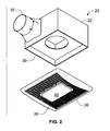
- FIG. 1 is a perspective view of an exhaust fan assembly according to an example of the present subject matter.
- FIG. 2 is an exploded perspective view of the exhaust fan assembly depicted in FIG. 1 .
- FIG. 3 is a side view of the exhaust fan assembly depicted in FIG. 1 .
- FIG. 4 is an exploded perspective view of a grille and light module assembly according to an example of the present subject matter.
- FIG. 5 is a bottom view of the grille and light module assembly depicted in FIG. 4 .
- FIG. 6 is a bottom view of a light module assembly according to an example of the present subject matter.
- FIG. 7 is a side view of the light module assembly according to an example.
- FIG. 8 is a perspective view of a grille and light module assembly according to an example of the present subject matter.
- FIG. 9 is a front view of the grille and light module assembly depicted in FIG. 8 .
- FIG. 10 is a side view of the grille and light module assembly depicted in FIG. 8 .
- FIG. 11 is a top view of the grille and light module assembly depicted in FIG. 8 .
- FIG. 12 is a bottom view of the grille and light module assembly depicted in FIG. 8 .
- FIG. 13 is a perspective view of a grille and light module assembly according to an example of the present subject matter.
- FIG. 14 is a front view of the grille and light module assembly depicted in FIG. 13 .
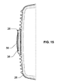
- FIG. 15 is a side view of the grille and light module assembly depicted in FIG. 13 .
- FIG. 16 is a top view of the grille and light module assembly depicted in FIG. 13 .
- FIG. 17 is a bottom view of the grille and light module assembly depicted in FIG. 13 .
- FIG. 18 is a cross-sectional side view of the grille and light module assembly depicted in FIG. 8 .
- FIG. 19 is a perspective view of a grille and light module assembly according to an example of the present subject matter.
- FIG. 20 is a front view of the grille and light module assembly depicted in FIG. 19 .
- FIG. 21 is a side view of the grille and light module assembly depicted in FIG. 19 .
- FIG. 22 is a top view of the grille and light module assembly depicted in FIG. 19 .
- FIG. 23 is a bottom view of the grille and light module assembly depicted in FIG. 19 .
- FIG. 24 is a perspective view of a grille and light module assembly according to an example of the present subject matter.
- FIG. 25 is a front view of the grille and light module assembly depicted in FIG. 24 .
- FIG. 26 is a side view of the grille and light module assembly depicted in FIG. 24 .
- FIG. 27 is a top view of the grille and light module assembly depicted in FIG. 24 .
- FIG. 28 is a bottom view of the grille and light module assembly depicted in FIG. 24 .
- FIG. 29 is a cross-sectional side view of the grille and light module assembly depicted in FIG. 19 .
- an exhaust fan assembly 20 includes a fan housing 22 , a fan 24 , a grille 26 and a light module 28 .
- the fan housing 22 can define an interior space and an inlet opening 30 and an outlet opening 32 .
- the fan 24 can be positioned within the interior space and operable to draw air through the inlet opening 30 and expel air through the outlet opening 32 .
- the fan 24 is a rotary fan positioned proximate the outlet opening 32 to increase the interior space between the inlet opening 30 and the fan 24 .
- the grille 26 is positioned within the inlet opening 30 to visually obscure the interior space and the fan 24 .
- the light module 28 can include a module housing 34 , at least one light emitting element 36 and a semitransparent cover 38 .
- the module housing 34 can define an interior space for receiving at least one light emitting element 36 .
- the light emitting element 36 can be a light emitting diode, incandescent light bulb or other light emitting device.
- a circuit board 39 is positioned within the module housing 34 .
- the circuit board 39 is configured to receive each light emitting element 36 and can position a plurality of light emitting elements 36 in a planar array.
- the semitransparent cover 38 is engagable to the module housing 34 . In an example, the semitransparent cover 38 is between about 40% and about 80% translucent.
- the semitransparent cover 38 can include a window portion 40 having an inner surface 42 .
- the each light emitting element 36 is positioned within the module housing 34 such that the light emitting element 36 is at least a minimum predetermined distance.
- the minimum predetermined distance can correspond to about the distance between each light emitting element 36 and its adjacent light emitting element 36 .
- each light emitting element 36 can be equidistance from each light emitting element 36 .
- each light emitting element 36 can be a first distance from an adjacent light emitting element 36 along a first axis and a second distance from an adjacent light emitting element 36 along a second axis, where the second distance is different from the first distance.
- the minimum predetermined distance can correspond to the maximum distance between each light emitting element 36 and the adjacent light emitting element 36 .
- the minimum predetermined distance can correspond to the minimum distance between each light emitting element 36 and the adjacent light emitting element 36 . The minimum distance improves diffraction of light from the light emitting elements 36 .
- the grille 26 defines a module opening 44 for receiving the light module 28 .
- the light module 28 can include at least one grille engagement feature 44 for securing the light module 28 .
- the grille 26 can include at least one module engagement feature 46 corresponding to the grille engagement feature 44 .
- the grille engagement features 44 and the module engagement features 46 can be snap in features for tool-less engagement of the light module 28 to the grille 26 .
- the module housing 34 can include a back surface 48 .
- the light module 28 is mounted on the grille 26 such that the back surface 48 of the module housing 34 is at least a minimum predetermined distance from the fan 24 . In an example, the minimum predetermined distance can be up to about 2 inches. The minimum distance between the fan and the back surface 48 of the module housing 34 reduces the interference of the light module 28 on the flow of air through the interior space within the fan housing 22 .
- the light module 28 can further include a connector plug 50 connectable to a wall outlet or other outlet for the house current. In this configuration, the light module 28 can be directly plugged into the house current. Similarly, this arrangement allows the light module 28 to be removed from the grille 26 and replaced with minimal or without tools.
- the light module 28 can also include a power cable 52 operably connecting the connector plug 50 to the light emitting elements 36 .
- the light module 28 can include a transformer positioned within the module housing 34 or at the connector plug 50 to change the voltage to levels appropriate for the light emitting elements 36 .
- the semi-transparent cover 38 can have window portion 40 and at least one vent port 56 .
- the window portion 40 can be positioned proximate the center of the cover 38 to correspond the portion where the majority of the light generated by the light emitting element 36 is transmitted through the semi-transparent cover 38 .
- the at least one vent port 56 can be positioned along an edge of the cover 38 to minimize refraction or distortion of the light by the vent port 56 .
- each vent port 56 can have depth for creating a pathway to guide the heated air radially outward from the window portion 40 .
- outwardly directed heated air will minimize heat distortion of light transmitted through the lens portion that can be created by the heated air.
- the heated air stream can be directed to intersect with the air being ventilated through the grille 26 to further dissipate the heat and/or dissipate the heat more quickly.
- the semi-transparent cover 38 can have a plurality of vent ports 56 including at least one inlet vent port 56 A and at least one outlet vent port 56 B positioned opposite the inlet vent port 56 A.
- air can be drawn into the semi-transparent cover 38 through the inlet vent port 56 A and out through the outlet vent port 56 B.
- the circulating air can more rapidly cool the light emitting elements 36 and further dissipate any heated air that can create heat mirages.
- the designation of the inlet vent port 56 A and the outlet vent port 56 B are intended to be illustrative and not intended to fix operation of the designated vent port 56 as any vent port 56 can operate as an inlet port or an outlet port depending on the ambient air conditions and the heating conditions within the cover 38 .
- the semi-transparent cover 38 includes two pairs of inlet vent ports 56 A and outlet vent ports 56 B. It is contemplated that the semi-transparent cover 38 can include a plurality of inlet vent ports 56 A and outlet vent ports 56 B.
- Example 1 can include subject matter, such as can include a light module 28 for an exhaust fan assembly 20 including a module housing 34 ; a semitransparent cover 38 coupled to the housing 34 to define an enclosed space; and at least one light emitting element 36 positioned within the housing 34 and oriented to emit light toward the semitransparent cover 38 .
- a light module 28 for an exhaust fan assembly 20 including a module housing 34 ; a semitransparent cover 38 coupled to the housing 34 to define an enclosed space; and at least one light emitting element 36 positioned within the housing 34 and oriented to emit light toward the semitransparent cover 38 .
- Example 2 can include, or can optionally be combined with the subject matter of Example 1, to optionally include that the semitransparent cover 38 including a window portion 40 having an inner surface 42 .
- the light emitting element 36 can be positioned within the interior space a predetermined minimum distance from the inner surface 42 of the window portion 40 .
- Example 3 can include, or can optionally be combined with the subject matter of Example 2, to optionally include that the semitransparent cover 38 has a sidewall for positioning the inner surface 42 of the window portion 40 the predetermined minimum distance.
- Example 4 can include, or can optionally be combined with the subject matter of Example 2, to optionally include that the predetermined minimum distance corresponds to about a spacing distance between two adjacent light emitting elements 36 .
- Example 5 can include, or can optionally be combined with the subject matter of one or any combination of the preceding claims, to optionally include that the housing 34 further includes at least one mounting feature that can be engaged to a grille 26 of the exhaust fan assembly 20 .
- Example 6 can include, or can optionally be combined with the subject matter of Example 4, to optionally include that the grille 26 defines an opening for receiving the housing 34 .
- Example 7 can include, or can optionally be combined with the subject matter of one or any combination of the preceding claims, to optionally include that the light module 28 includes a plurality of light emitting elements 36 .
- the plurality of the light emitting elements 36 can be arranged in an planar array.
- Example 8 can include, or can optionally be combined with the subject matter of one or any combination of the preceding claims, to optionally include a power cable 52 connectable to a wall outlet and a connector cable operably connecting the power cable 52 to each light emitting elements 36 .
- Example 9 can include, or can optionally be combined with the subject matter of one or any combination of the preceding claims, to optionally include that the at least one light emitting element 36 can comprise at least one of a light emitting diode and an incandescent bulb.
- Example 10 can include, or can optionally be combined with the subject matter of one or any combination of the preceding claims, to optionally include that the semitransparent cover 38 includes at least one vent port for dissipating heat from within the light module 28 .
- Example 11 can include subject matter, such as can include an exhaust fan assembly 20 including a fan housing defining an interior space and including an inlet opening and an outlet opening; a fan positioned within the interior space, the fan being operable to draw air through the inlet opening and out the outlet opening; a grille 26 engaged to the fan housing within the inlet opening; and a light module 28 .
- the light module 28 can include a module housing 34 engaged to the grille 26 , a semitransparent cover 38 coupled to the housing 34 to define an enclosed space, and at least one light emitting element 36 positioned within the housing 34 and oriented to emit light toward the semitransparent cover 38 .
- Example 12 can include, or can optionally be combined with the subject matter of Example 11, to optionally include that the module housing 34 includes a rear face.
- Example 13 can include, or can optionally be combined with the subject matter of Example 12, to optionally include that the fan is at least up to about 2 inches from the rear face of the module housing 34 .
- Example 14 can include, or can optionally be combined with the subject matter of one or any combination of the preceding claims, to optionally include that the grille 26 defines a module opening for receiving the light module 28 .
- Example 15 can include, or can optionally be combined with the subject matter of Example 14, to optionally include that the housing 34 further includes at least one mounting feature can be engaged to a grille 26 of the exhaust fan assembly 20 .
- Example 16 can include, or can optionally be combined with the subject matter of one or any combination of the preceding claims, to optionally include that the semitransparent cover 38 including a window portion 40 having an inner surface 42 .
- the light emitting element 36 can be positioned within the interior space a predetermined minimum distance from the inner surface 42 of the window portion 40 .
- Example 17 can include, or can optionally be combined with the subject matter of Example 16, to optionally include that the semitransparent cover 38 having a sidewall for positioning the inner surface 42 of the window portion 40 the predetermined minimum distance.
- Example 18 can include, or can optionally be combined with the subject matter of Example 16, to optionally include that the predetermined minimum distance corresponds to about a spacing distance between two adjacent light emitting elements 36 .
- Example 19 can include, or can optionally be combined with the subject matter of one or any combination of the preceding claims, to optionally include that the light module 28 includes a plurality of light emitting elements 36 .
- the plurality of the light emitting diodes can be arranged in an planar array.
- Example 20 can include, or can optionally be combined with the subject matter of one or any combination of the preceding claims, to optionally include a power cable 52 connectable to a wall outlet and a connector cable operably connecting the power cable 52 to each light emitting elements 36 .
- Example 21 can include, or can optionally be combined with the subject matter of one or any combination of the preceding claims, to optionally include that the at least one light emitting element 36 can comprise at least one of a light emitting diode and an incandescent bulb.
- Example 22 can include, or can optionally be combined with the subject matter of one or any combination of the preceding claims, to optionally include that the semitransparent cover 38 includes at least one vent port 56 for dissipating heat from within the light module 28 .
- the terms “a” or “an” are used, as is common in patent documents, to include one or more than one, independent of any other instances or usages of “at least one” or “one or more.”
- the term “or” is used to refer to a nonexclusive or, such that “A or B” includes “A but not B,” “B but not A,” and “A and B,” unless otherwise indicated.
- Method examples described herein can be machine or computer-implemented at least in part. Some examples can include a computer-readable medium or machine-readable medium encoded with instructions operable to configure an electronic device to perform methods as described in the above examples.
- An implementation of such methods can include code, such as microcode, assembly language code, a higher-level language code, or the like. Such code can include computer readable instructions for performing various methods. The code may form portions of computer program products. Further, in an example, the code can be tangibly stored on one or more volatile, non-transitory, or non-volatile tangible computer-readable media, such as during execution or at other times.
- Examples of these tangible computer-readable media can include, but are not limited to, hard disks, removable magnetic disks, removable optical disks (e.g., compact disks and digital video disks), magnetic cassettes, memory cards or sticks, random access memories (RAMs), read only memories (ROMs), and the like.
Abstract
Description
Claims (20)
Priority Applications (1)
| Application Number | Priority Date | Filing Date | Title |
|---|---|---|---|
| US14/843,648 US9816699B2 (en) | 2014-09-05 | 2015-09-02 | Exhaust fan light module |
Applications Claiming Priority (3)
| Application Number | Priority Date | Filing Date | Title |
|---|---|---|---|
| US201462046689P | 2014-09-05 | 2014-09-05 | |
| US201562101825P | 2015-01-09 | 2015-01-09 | |
| US14/843,648 US9816699B2 (en) | 2014-09-05 | 2015-09-02 | Exhaust fan light module |
Publications (2)
| Publication Number | Publication Date |
|---|---|
| US20160069561A1 US20160069561A1 (en) | 2016-03-10 |
| US9816699B2 true US9816699B2 (en) | 2017-11-14 |
Family
ID=55411816
Family Applications (1)
| Application Number | Title | Priority Date | Filing Date |
|---|---|---|---|
| US14/843,648 Expired - Fee Related US9816699B2 (en) | 2014-09-05 | 2015-09-02 | Exhaust fan light module |
Country Status (4)
| Country | Link |
|---|---|
| US (1) | US9816699B2 (en) |
| CN (1) | CN105402700B (en) |
| CA (1) | CA2902906C (en) |
| HK (1) | HK1221004A1 (en) |
Families Citing this family (43)
| Publication number | Priority date | Publication date | Assignee | Title |
|---|---|---|---|---|
| US20090170421A1 (en) | 2008-01-02 | 2009-07-02 | Adrian John R | Grille |
| USD743520S1 (en) | 2013-06-20 | 2015-11-17 | Broan-Nutone Llc | Range hood |
| USD736903S1 (en) | 2014-05-01 | 2015-08-18 | Broan-Nutone Llc | Down draft grill |
| CA2902906C (en) | 2014-09-05 | 2022-07-26 | Broan-Nutone Llc | Exhaust fan light module |
| US11359806B2 (en) * | 2014-10-15 | 2022-06-14 | Delta Electronics, Inc. | Ventilation system |
| USD779050S1 (en) * | 2015-01-08 | 2017-02-14 | Broan-Nutone Llc | Ventilator grill |
| USD784511S1 (en) | 2015-01-08 | 2017-04-18 | Broan-Nutone Llc | Ventilator grill |
| USD784512S1 (en) | 2015-01-08 | 2017-04-18 | Broan-Nutone Llc | Ventilator grill |
| USD778425S1 (en) | 2015-01-08 | 2017-02-07 | Broan-Nutone Llc | Ventilator grill |
| USD778424S1 (en) * | 2015-01-08 | 2017-02-07 | Broan-Nutone Llc | Ventilator grill |
| USD826391S1 (en) | 2015-05-19 | 2018-08-21 | Broan-Nutone Llc | Vent hood |
| USD804627S1 (en) | 2015-05-19 | 2017-12-05 | Broan-Nutone Llc | Vent hood |
| USD814009S1 (en) | 2015-05-19 | 2018-03-27 | Broan-Nutone, Llc | Vent hood |
| CA165306S (en) | 2015-05-19 | 2017-01-23 | Broan Nu Tone Llc | Vent hood |
| USD785777S1 (en) | 2015-08-31 | 2017-05-02 | Broan-Nutone Llc | Vent hood |
| USD799678S1 (en) * | 2015-09-14 | 2017-10-10 | Broan-Nutone Llc | Ventilation grill |
| USD800892S1 (en) | 2015-09-14 | 2017-10-24 | Broan-Nutone Llc | Ventilation grill |
| USD822821S1 (en) | 2015-09-14 | 2018-07-10 | Broan-Nutone, Llc | Ventilation grill |
| USD799679S1 (en) * | 2015-09-14 | 2017-10-10 | Broan-Nutone Llc | Ventilation grill |
| USD800294S1 (en) * | 2015-09-14 | 2017-10-17 | Broan-Nutone Llc | Ventilation grill |
| USD815724S1 (en) | 2015-09-14 | 2018-04-17 | Broan-Nutone Llc | Ventilation grill |
| USD800295S1 (en) * | 2015-09-14 | 2017-10-17 | Broan-Nutone Llc | Ventilation grill |
| USD816206S1 (en) | 2015-09-14 | 2018-04-24 | Broan-Nutone Llc | Ventilation grill |
| USD799677S1 (en) * | 2015-09-14 | 2017-10-10 | Broan-Nutone Llc | Ventilation grill |
| USD774018S1 (en) | 2015-10-06 | 2016-12-13 | Broan-Nutone Llc | Wireless speaker |
| USD897521S1 (en) | 2016-10-14 | 2020-09-29 | Broan-Nutone Llc | Vent hood |
| JP6846595B2 (en) * | 2016-12-28 | 2021-03-24 | パナソニックIpマネジメント株式会社 | Ventilation fan grill and ventilation fan |
| US20180313558A1 (en) * | 2017-04-27 | 2018-11-01 | Cisco Technology, Inc. | Smart ceiling and floor tiles |
| USD892296S1 (en) * | 2018-05-21 | 2020-08-04 | Broan-Nutone Llc | Grille assembly for a bathroom ventilation fan |
| USD879284S1 (en) * | 2018-05-21 | 2020-03-24 | Broan-Nutone Llc | Grille assembly for a bathroom ventilation fan |
| USD895783S1 (en) | 2018-05-22 | 2020-09-08 | Broan-Nutone Llc | Grille assembly for a bathroom ventilation fan |
| WO2019226791A1 (en) * | 2018-05-22 | 2019-11-28 | Broan-Nutone Llc | Ventilation fan system with advanced chromatherapy controls |
| USD909560S1 (en) | 2018-11-28 | 2021-02-02 | Broan-Nutone Llc | Ventilation grille |
| USD902372S1 (en) | 2018-11-28 | 2020-11-17 | Broan-Nutone Llc | Ventilation grille |
| USD943730S1 (en) | 2018-11-28 | 2022-02-15 | Broan-Nutone Llc | Ventilation grille |
| USD946136S1 (en) | 2018-11-28 | 2022-03-15 | Broan-Nutone Llc | Ventilation grille |
| USD908861S1 (en) | 2018-11-28 | 2021-01-26 | Broan-Nutone Llc | Ventilation grille |
| USD898896S1 (en) | 2019-01-22 | 2020-10-13 | Broan-Nutone Llc | Ventilation grille |
| USD899582S1 (en) | 2019-01-22 | 2020-10-20 | Broan-Nutone Llc | Ventilation grille |
| US11300305B2 (en) | 2019-02-15 | 2022-04-12 | Broan-Nutone Llc | Grille attachment feature for a ventilation system |
| US11326792B2 (en) | 2019-02-15 | 2022-05-10 | Broan-Nutone Llc | Grille attachment system for a ventilation system |
| USD946137S1 (en) | 2019-05-01 | 2022-03-15 | Broan-Nutone Llc | Ventilation grille |
| KR102363593B1 (en) * | 2019-12-26 | 2022-02-16 | 주식회사 알토 | Integrated lighting unit of air conditioning and lighting |
Citations (20)
| Publication number | Priority date | Publication date | Assignee | Title |
|---|---|---|---|---|
| US2189008A (en) * | 1937-08-07 | 1940-02-06 | Franz J Kurth | Ventilating device |
| US3701895A (en) * | 1971-06-30 | 1972-10-31 | Thomas Industries Inc | Combined lighting and ventilating fixture |
| US3785271A (en) * | 1972-02-07 | 1974-01-15 | Ventrola Mfg Co | New low profile ventilator apparatus means |
| US20060285310A1 (en) | 2005-06-15 | 2006-12-21 | Shing-Jy Shyu | Ceiling fan light LED assembly device |
| US7203416B2 (en) * | 2003-11-21 | 2007-04-10 | Broan-Nutone Llc | Ventilating and heating apparatus with heater shielded by tapered discharge duct |
| US20080285271A1 (en) * | 2007-05-04 | 2008-11-20 | Philips Solid-State Lighting Solutions, Inc. | Led-based fixtures and related methods for thermal management |
| US7455432B2 (en) * | 2003-11-14 | 2008-11-25 | Broan-Nutone Llc | Lighting and ventilating apparatus and method |
| US20090170421A1 (en) * | 2008-01-02 | 2009-07-02 | Adrian John R | Grille |
| US20100009621A1 (en) * | 2008-07-11 | 2010-01-14 | Hsieh Te-Hsuan | External rotor brushless dc motor driven exhaust fan |
| US8066802B2 (en) | 2006-02-28 | 2011-11-29 | Airsonett Ab | Method and device for providing a zone of clean air at an operation area and use of said device |
| US20120087132A1 (en) * | 2010-10-11 | 2012-04-12 | Broan-Nutone Llc | Lighting and Ventilating System and Method |
| US20130088855A1 (en) * | 2011-10-11 | 2013-04-11 | Delta Electronics, Inc. | Ventilation fan with lights |
| US8439532B2 (en) | 2008-08-29 | 2013-05-14 | Osram Gesellschaft Mit Beschraenkter Haftung | Lighting device to be installed in a panel |
| US8591066B2 (en) | 2008-08-19 | 2013-11-26 | Spectronics Corporation | Modular lamp head and assembly for non-destructive testing |
| US20130343052A1 (en) | 2012-06-25 | 2013-12-26 | Teng-Chia Yen | LED light for a ceiling fan |
| US20140043834A1 (en) | 2008-12-12 | 2014-02-13 | Bridgelux, Inc. | Light emitting diode luminaire |
| USD705417S1 (en) * | 2013-02-11 | 2014-05-20 | Delta Electronics, Inc. | Ventilation fan with LED |
| US8992035B2 (en) | 2012-09-05 | 2015-03-31 | Panasonic Ecology Systems Guangdong Co., Ltd. | Lighting device for ventilating fan |
| US9103104B1 (en) * | 2010-10-08 | 2015-08-11 | Chien Luen Industries Co., Ltd., Inc. | Bath fan and heater with cover having adjustable luver or depressible fastener and depressible release |
| CN105402700A (en) | 2014-09-05 | 2016-03-16 | 布罗恩-努托恩有限责任公司 | Exhaust fan light module |
Family Cites Families (5)
| Publication number | Priority date | Publication date | Assignee | Title |
|---|---|---|---|---|
| BRPI0822042A2 (en) * | 2008-01-18 | 2015-07-28 | Johnson & Johnson Ltd | Ventilation and cooling device for an imaging system |
| CN201715409U (en) * | 2010-06-13 | 2011-01-19 | 钱江涛 | Built-in soft light led fluorescent lamp |
| CN201747642U (en) * | 2010-08-11 | 2011-02-16 | 何世健 | Pipeline type exhaust fan with lamp |
| US8485696B2 (en) * | 2010-10-11 | 2013-07-16 | Broan NuTone, LLC | Lighting and ventilating system and method |
| CN203384682U (en) * | 2013-06-25 | 2014-01-08 | 彩虹集团公司 | LED bottom lighting panel lamp |
-
2015
- 2015-09-02 CA CA2902906A patent/CA2902906C/en active Active
- 2015-09-02 US US14/843,648 patent/US9816699B2/en not_active Expired - Fee Related
- 2015-09-06 CN CN201510660426.4A patent/CN105402700B/en active Active
-
2016
- 2016-07-29 HK HK16109092.0A patent/HK1221004A1/en unknown
Patent Citations (20)
| Publication number | Priority date | Publication date | Assignee | Title |
|---|---|---|---|---|
| US2189008A (en) * | 1937-08-07 | 1940-02-06 | Franz J Kurth | Ventilating device |
| US3701895A (en) * | 1971-06-30 | 1972-10-31 | Thomas Industries Inc | Combined lighting and ventilating fixture |
| US3785271A (en) * | 1972-02-07 | 1974-01-15 | Ventrola Mfg Co | New low profile ventilator apparatus means |
| US7455432B2 (en) * | 2003-11-14 | 2008-11-25 | Broan-Nutone Llc | Lighting and ventilating apparatus and method |
| US7203416B2 (en) * | 2003-11-21 | 2007-04-10 | Broan-Nutone Llc | Ventilating and heating apparatus with heater shielded by tapered discharge duct |
| US20060285310A1 (en) | 2005-06-15 | 2006-12-21 | Shing-Jy Shyu | Ceiling fan light LED assembly device |
| US8066802B2 (en) | 2006-02-28 | 2011-11-29 | Airsonett Ab | Method and device for providing a zone of clean air at an operation area and use of said device |
| US20080285271A1 (en) * | 2007-05-04 | 2008-11-20 | Philips Solid-State Lighting Solutions, Inc. | Led-based fixtures and related methods for thermal management |
| US20090170421A1 (en) * | 2008-01-02 | 2009-07-02 | Adrian John R | Grille |
| US20100009621A1 (en) * | 2008-07-11 | 2010-01-14 | Hsieh Te-Hsuan | External rotor brushless dc motor driven exhaust fan |
| US8591066B2 (en) | 2008-08-19 | 2013-11-26 | Spectronics Corporation | Modular lamp head and assembly for non-destructive testing |
| US8439532B2 (en) | 2008-08-29 | 2013-05-14 | Osram Gesellschaft Mit Beschraenkter Haftung | Lighting device to be installed in a panel |
| US20140043834A1 (en) | 2008-12-12 | 2014-02-13 | Bridgelux, Inc. | Light emitting diode luminaire |
| US9103104B1 (en) * | 2010-10-08 | 2015-08-11 | Chien Luen Industries Co., Ltd., Inc. | Bath fan and heater with cover having adjustable luver or depressible fastener and depressible release |
| US20120087132A1 (en) * | 2010-10-11 | 2012-04-12 | Broan-Nutone Llc | Lighting and Ventilating System and Method |
| US20130088855A1 (en) * | 2011-10-11 | 2013-04-11 | Delta Electronics, Inc. | Ventilation fan with lights |
| US20130343052A1 (en) | 2012-06-25 | 2013-12-26 | Teng-Chia Yen | LED light for a ceiling fan |
| US8992035B2 (en) | 2012-09-05 | 2015-03-31 | Panasonic Ecology Systems Guangdong Co., Ltd. | Lighting device for ventilating fan |
| USD705417S1 (en) * | 2013-02-11 | 2014-05-20 | Delta Electronics, Inc. | Ventilation fan with LED |
| CN105402700A (en) | 2014-09-05 | 2016-03-16 | 布罗恩-努托恩有限责任公司 | Exhaust fan light module |
Also Published As
| Publication number | Publication date |
|---|---|
| US20160069561A1 (en) | 2016-03-10 |
| CA2902906C (en) | 2022-07-26 |
| CN105402700B (en) | 2021-01-26 |
| CA2902906A1 (en) | 2016-03-05 |
| CN105402700A (en) | 2016-03-16 |
| HK1221004A1 (en) | 2017-05-19 |
Similar Documents
| Publication | Publication Date | Title |
|---|---|---|
| US9816699B2 (en) | Exhaust fan light module | |
| US8319408B1 (en) | LED lamp with simplified structure | |
| TWI491832B (en) | Lamp | |
| US9303859B2 (en) | Illuminating ventilator | |
| US8960965B2 (en) | Lamp | |
| US20130308319A1 (en) | Led lamp | |
| US20120275163A1 (en) | Lighting device and light source module thereof | |
| US10006612B2 (en) | LED lighting assembly structure | |
| EP3208522B1 (en) | Omnidirectional light emission led lamp | |
| US9671101B2 (en) | Lighting device and luminaire | |
| TWI414721B (en) | Lamp | |
| TWI414722B (en) | Lamp | |
| US8622591B1 (en) | LED lamp scattering heat by exchanging currents | |
| TWI481798B (en) | Lamp | |
| CN107683388B (en) | Repeatable blind fitting for a luminaire | |
| JP2016021366A (en) | LED lighting device | |
| CN203349238U (en) | Light-emitting diode (LED) bulb type industrial mining lamp | |
| JP2016096120A (en) | Lamp device | |
| CN208900389U (en) | A kind of LED luminous heat radiation fan | |
| US9846351B2 (en) | Projector and heat dissipating method for projector | |
| CN205896895U (en) | Light -emitting diode (LED) ceiling lamp | |
| CN205331918U (en) | Area source LED bar lamp | |
| CN208605945U (en) | Lamp assembly | |
| EP3058271B1 (en) | Watertight lighting fixture | |
| JP6385239B2 (en) | Illuminated panel |
Legal Events
| Date | Code | Title | Description |
|---|---|---|---|
| AS | Assignment |
Owner name: BROAN-NUTONE LLC, WISCONSIN Free format text: ASSIGNMENT OF ASSIGNORS INTEREST;ASSIGNORS:JONAS, KENNETH JOHN;JACAK, COREY SCOTT;PUFFER, BENJAMIN THORPE;AND OTHERS;REEL/FRAME:042638/0296 Effective date: 20150908 |
|
| STCF | Information on status: patent grant |
Free format text: PATENTED CASE |
|
| AS | Assignment |
Owner name: GOLDMAN SACHS BANK USA, AS COLLATERAL AGENT, NEW YORK Free format text: SECURITY INTEREST;ASSIGNORS:BROAN-NUTONE LLC;NORTEK AIR SOLUTIONS, LLC;NORTEK GLOBAL HVAC, LLC;AND OTHERS;REEL/FRAME:056647/0868 Effective date: 20210621 Owner name: U.S. BANK NATIONAL ASSOCIATION, AS COLLATERAL AGENT, TENNESSEE Free format text: SECURITY INTEREST;ASSIGNORS:BROAN-NUTONE LLC;NORTEK AIR SOLUTIONS, LLC;NORTEK GLOBAL HVAC, LLC;AND OTHERS;REEL/FRAME:056650/0303 Effective date: 20210621 |
|
| FEPP | Fee payment procedure |
Free format text: MAINTENANCE FEE REMINDER MAILED (ORIGINAL EVENT CODE: REM.); ENTITY STATUS OF PATENT OWNER: LARGE ENTITY |
|
| LAPS | Lapse for failure to pay maintenance fees |
Free format text: PATENT EXPIRED FOR FAILURE TO PAY MAINTENANCE FEES (ORIGINAL EVENT CODE: EXP.); ENTITY STATUS OF PATENT OWNER: LARGE ENTITY |
|
| STCH | Information on status: patent discontinuation |
Free format text: PATENT EXPIRED DUE TO NONPAYMENT OF MAINTENANCE FEES UNDER 37 CFR 1.362 |
|
| FP | Lapsed due to failure to pay maintenance fee |
Effective date: 20211114 |