USRE43856E1 - Hybrid public/private wireless network with seamless roaming - Google Patents
Hybrid public/private wireless network with seamless roaming Download PDFInfo
- Publication number
- USRE43856E1 USRE43856E1 US12/291,334 US29133408A USRE43856E US RE43856 E1 USRE43856 E1 US RE43856E1 US 29133408 A US29133408 A US 29133408A US RE43856 E USRE43856 E US RE43856E
- Authority
- US
- United States
- Prior art keywords
- niu
- mobile subscriber
- home
- atc
- network
- Prior art date
- Legal status (The legal status is an assumption and is not a legal conclusion. Google has not performed a legal analysis and makes no representation as to the accuracy of the status listed.)
- Expired - Fee Related, expires
Links
Images


Classifications
-
- H—ELECTRICITY
- H04—ELECTRIC COMMUNICATION TECHNIQUE
- H04W—WIRELESS COMMUNICATION NETWORKS
- H04W8/00—Network data management
- H04W8/02—Processing of mobility data, e.g. registration information at HLR [Home Location Register] or VLR [Visitor Location Register]; Transfer of mobility data, e.g. between HLR, VLR or external networks
- H04W8/08—Mobility data transfer
- H04W8/12—Mobility data transfer between location registers or mobility servers
-
- H—ELECTRICITY
- H04—ELECTRIC COMMUNICATION TECHNIQUE
- H04W—WIRELESS COMMUNICATION NETWORKS
- H04W84/00—Network topologies
- H04W84/02—Hierarchically pre-organised networks, e.g. paging networks, cellular networks, WLAN [Wireless Local Area Network] or WLL [Wireless Local Loop]
- H04W84/04—Large scale networks; Deep hierarchical networks
Definitions
- This invention relates generally to communications systems having mobile subscribers and, more particularly to wireless private branch exchange systems used together with public mobile communication systems.
- indoor cellular systems in the prior art can either be part of private system, such as a wireless Private Branch Exchange (PBX) or they can be extensions of the public network (PSTN) to an indoor space.
- PBX wireless Private Branch Exchange
- PSTN public network
- the alternate approach in the prior art for seamless in and out of building mobility involves extending the public cellular network indoors.
- the user continues to be treated as if in the public space but the call uses private infrastructure when indoors.
- the users' phone number and switch features and extension dialing are determined by the public cellular system and the carrier's switch, not the user's PBX (which may indeed be purely virtual). This requires the user to adopt different dialing procedures for his wireless phone than he would use for his PBX.
- any wired phone connected to a user's PBX would not be linked to the user's wireless phone.
- Each network interface unit in the partition consists of a plurality of Network Interface Units (NIU) connected between a wireless access subsystem (WAS) and the network's air Traffic Controller (ATC).
- NIU may also be connected to a local exchange switch or to a PBX.
- Each subscriber of the local exchange (LE) or any PBX is assigned a single home NIU connected to the subscriber's assigned port on the local exchange or the PBX, respectively.
- the ATC registers when subscribers move outside the coverage area of their Home NIU. When a subscriber wants to make a call from the coverage area of a NIU different from his or her Home NIU, the A TC routes the call to the Home NIU which sets up the call to the subscriber's assigned port on the PBX or LE.
- the ATC routes the incoming calls arriving at the Home NIU from the subscriber's assigned port on the PBX or LE to the Visited NIU where the subscriber can be reached.
- the connection is always through the switch port assigned to the subscriber A making roaming entirely transparent to the switch (local exchange or PBX) and switch billing systems.
- the ATC acts as a combination visited location register/home location register (VLR/HLR) and crossconnect switch between Visited NIU and Home NIU.
- one aspect of the present invention is embodied in a communications system connecting mobile subscriber devices to at least one of a PSTN and a plurality of PBX networks comprising a plurality of network interface units coupled to one of a PSTN and a PBX network.
- Each of the plurality of network interface units have a predetermined coverage area in which a plurality of mobile subscriber devices roam.
- Each mobile subscriber device is assigned to one network interface unit designated a home network interface unit, and the mobile subscriber device receives a port assignment through the home network interface unit from one of the PSTN and the PBX coupled to the home network interface unit.
- the PSTN port assignment determines the mobile subscriber device directory number
- the PBX network port assignment determines the mobile subscriber device extension number.
- a wireless access unit is coupled to each of the plurality of network interface units and provides wireless connection between the network interface unit and a mobile subscriber device within the coverage area of the network interface unit.
- a programmable cross-connect device connects the plurality of network interface units and dynamically cross-connects calls between the home network interface unit of the mobile subscriber device and a visited network interface unit as part of call origination and termination process.
- the visited network interface unit covers a geographic region within which the mobile subscriber device is roaming.
- Another embodiment of the present invention teaches a method of providing communication services for a plurality of mobile subscriber devices and at least one of a PSTN and one of a plurality of PBX networks comprising, coupling a plurality of network interface units to one of a PSTN and a PBX network, wherein each of the plurality of network interface units have a predetermined coverage area.
- Each of the mobile subscriber devices are assigned to only one of the plurality of network interface units considered a home network interface unit, and each of the mobile subscriber devices receive a port assignment through the home network interface unit from one of the PSTN and the PBX network coupled to the home network interface unit, wherein a wireless access unit coupled to each of the plurality of network interface units and providing wireless connection between the network interface unit and a mobile subscriber device within the coverage area of the network interface unit; and connecting a programmable cross-connect device to the plurality of network interface units and dynamically cross connecting calls between the home network interface unit of the mobile subscriber device and a visited network interface unit as part of call origination and termination process, the visited network interface unit covering a geographic region within which the mobile subscriber device is roaming.
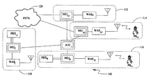
- FIG. 1 is a block diagram showing a hybrid public/private wireless network according to the teachings of the present invention
- FIG. 2 illustrates how the ATC of FIG. 1 routes incoming and outgoing calls for subscribers roaming outside their home network where their home NIU acts as the interface for a PSTN;
- FIG. 3 illustrates how the ATC of FIG. 1 routes incoming and outgoing calls for subscribers roaming outside their home network where their home NIU acts as the interface for a PBX;
- FIG. 4 is a connection diagram illustrating the mobile subscriber location registration process for a roaming subscriber, according to the present invention
- FIG. 5 is a connection diagram illustrating the a mobile subscriber call origination process according to the present invention.
- FIG. 6 is a connection diagram illustrating a mobile subscriber call termination process according to the present invention.
- FIG. 7 is a block diagram illustrating an inter-NIU handover process according to the present invention.
- FIG. 8 is a block diagram of the hybrid public/private wireless network according to a second embodiment of the present invention illustrating how inter-network capacity can be almost independent from intra-network capacity.
- the present invention is directed to a communication system comprising a partition of multiple sub-networks (each under the coverage of a network interface unit) providing mobility to subscriber devices roaming within and across these sub-networks.
- Each sub-network may be connected to a Private Branch Exchange or the Public Switched Telephone Network without requiring any changes to either the PBX or PSTN, and with the PBX or PSTN port assigned to a subscriber device determining the subscriber directory number and/or extension number as well as other subscriber specific features available only through the subscribers home PSTN or PBX system.
- the sub-network connected to the PBX or PSTN port corresponding to the subscriber's directory number is the subscriber's home sub-network.
- a programmable cross connect device provides full connectivity between all constituent sub-networks and dynamically cross connects calls between Home sub-network and Visited sub-network as part of the call origination and termination process, hence preserving all features available to a subscriber device within its home sub-network while the subscriber is roaming into another sub-network.
- FIG. 1 is a block diagram showing a hybrid public/private wireless network 100 according to one embodiment of the present invention.
- the hybrid public/private wireless network 100 consists of a plurality of network interface units (NIU) (also referred to as sub-networks) such as NIU A1 , NIU A2 , NIU B and NIU C .
- NIU network interface units
- Each NIU is coupled to either a PSTN network or a private branch exchange network (PBX).
- PBX private branch exchange network
- the NIU A1 and NIU A2 are coupled to the public switching network, PSTN 120 .
- Other NIU devices, such as NIU B and NIU C are coupled to the two private branch exchange networks PBX B and PBX C respectively.
- PBX B and PBX C are coupled to the two private branch exchange networks PBX B and PBX C respectively.
- sub-networks interface and sub-network interface units will be used interchangeably.
- Each NIU device is also coupled to a Wireless Access sub-system (WAS), also referred to as wireless access unit, allowing the NIU to communicate with a plurality of visiting or resident subscribers within its coverage region.
- a programmable cross connect device referred to as an Air Traffic Controller (ATC 1 ) couples the plurality of NIU devices within a given region to each other.
- ATC 1 Air Traffic Controller
- ATC 1 Air Traffic Controller
- Each network interface unit serves a different geographic region limited by the range of transmission and reception of its corresponding wireless access subsystem (WAS) to which that NIU is coupled.
- the coverage area corresponding to each NIU is shown in FIG. 1 .
- the shaded area 112 represents the coverage area of NIU A1 .
- area 114 represents to the coverage area under NIU A2
- 116 represents to the coverage area of NIU B
- area 118 represents the coverage area under NIU C .
- an interface device may be implemented as a computer with controllers.
- Each NIU may include an interface board for interfacing with the WAS. In this embodiment, the interfacing may take place over an E1 link.
- E1 is a European digital transmission format and is well known to those skilled in the art.
- the interface between the NIU and a PSTN or PBX network may take place over an analog interface, a T1 interface or other such interfaces.
- the interface devices are typically coupled to a class 5 switch in the PSTN.
- each interface is located in the respective region that it serves.
- the interfaces may be located in regions other than in the respective regions they serve. For example, the interfaces may be co-located.
- each NIU is also coupled to a WAS.
- NIU A1 is coupled to WAS A1 , NIU A2 to WAS A2 , NIU B to WAS B , and NIU C to WAS C .
- a WAS may include radio port controllers coupled to radio transceivers. Radio transceivers are used to communicate with mobile subscribers. Each radio transceiver may include radio ports and appropriate transceiver circuitry.
- Air traffic controllers couple the plurality of NIUs to each other.
- the ATC 1 couples NIU A1 , NIU A2 , NIU B , and NIU C .
- An ATC such as ATC 1 shown in FIG. 1 , may be implemented by dedicated circuits. In another embodiment, the ATC may be implemented by a computerized system and virtual circuits.
- the ATC circuitry may include bearer channels and control channels.
- the bearer circuitry provides a path for transmission of information, such as voice from a subscriber, to the correct NIU.
- the circuitry that routes between the interfaces (e.g., ATC) includes a cross connect, which is a switch that maps various incoming and outgoing lines. In one example, an ATC may have 30 multiplexed lines.
- the ATC circuitry may act as a controller and include an E1 interface. Typical bearer path for transmission of information may also occur over an E1 line.
- An NIU may be capable of handling a large number of subscribers assigned to it. In one embodiment, up to 10,000 subscribers and a large number of roaming subscribers may be serviced by a single device. It would be apparent to one skilled in the art that the size and capacity of the NIUs, the ATC and sizing of the connection between the NIU devices and the ATC circuitry are dependent on the amount of roaming traffic over that particular NIU and the ATC, and the desired grade of service for such roaming traffic.
- the mobile subscriber PS A2 is moving within the coverage area of the NIU A2 which is its home interface.
- the mobile subscriber PS A1 is shown outside of the coverage area of its home interface, NIU A1 , and is roaming within the coverage area of a new interface device, NIU B .
- Calls for and from PS A1 would still be routed through its home network interface unit NIU A1 coupled to its particular PSTN port within the public network PSTN 120 .
- the routing of calls for PS A1 would be further described in FIG. 2 , and compared to the routing of non-roaming mobile subscriber NIU A2 .
- FIG. 2 illustrates how the ATC routes incoming and outgoing calls for subscribers roaming outside their home network, where their home NIU acts as the interface for a Public-switched telephone network (PSTN).
- PSTN Public-switched telephone network
- the mobile subscriber PS A1 is shown to be roaming outside the coverage of its home NIU, NIU A1 .
- Each network interface unit NIU emits a unique paging identifier through its corresponding wireless access sub-system.
- the mobile subscriber PS A1 transmits its unique identification along with a registration request to the new NIU, NIU B in this example. Since PS A1 is not assigned to NIU B , the NIU B forwards the registration request to the ATC 1 .
- ATC 1 If ATC 1 is aware of the mobile subscriber PS A1 , it updates its location register and forwards the registration request to NIU A1 the mobile subscriber, PS A1 's home NIU. If the ATC 1 does not recognize PS A1 , it sends the registration requests to all NIUs under its coverage such as NIU A1 , NIU A2 and NIU C as shown here but not to NIU B , the NIU originating the forwarded registration request. NIU A1 as the home NIU to which PS A1 is assigned would recognize the registration request and respond to it by sending an authentication request to the ATC who in turn forwards the response to NIU B .
- the home NIU, NIU A1 in this example, will update its database to reflect the current location of PS A1 , and may attempt to forward incoming calls for PS A1 directly to NIU B , routed through ATC 1 .
- each mobile subscriber may be programmed with the identity of its home NIU.
- the current NIU may be able to direct registration requests directly to the subscribers home NIU without the need to query the ATC 1 .
- the identity of the home NIU to which the mobile subscriber is assigned may be deduced from the mobile subscriber's unique identification number.
- the mobile subscriber identification number may be coded so as to have a unique prefix corresponding to its home network.
- NIU A1 When receiving an incoming call for PS A1 , its home NIU, NIU A1 in this example, will send out a page corresponding to the mobile subscriber, PS A1 in this example, via WAS A1 . NIU A1 will also send the page to the ATC 1 . Since the mobile subscriber PS A1 is roaming outside the coverage area of NIU A1 , the wireless access sub-system WAS A1 will not report a positive page acknowledgment. If ATC 1 knows about PS A1 , it will forward the page to the appropriate NIU under whose coverage PS A1 is currently located, or was most recently known to be. Otherwise, ATC 1 will forward the page to all NIUs under its coverage except the NIU originating the page, NIU A1 in this case.
- NIU B The NIU that currently has the PS A1 under its coverage, NIU B in this example, will respond to the page.
- ATC 1 will forward the page response to PS A1 's home NIU, NIU A1 , and establish a call path between the home NIU, NIU A1 and the visiting NIU, NIU A2 , through ATC 1 to the roaming subscriber PS A1 . Authentication and alerting will take place and the connection is established.
- the home NIU may keep track of the location of the mobile subscriber, and thus may be able to forward the incoming call through the ATC 1 , to the appropriate NIU (NIU B in this example), under whose coverage the mobile subscriber PS A1 is located.
- the home NIU may be able to establish a connection with its roaming mobile subscriber without querying the ATC 1 .
- NIU B When originating a call from PS A1 while under the coverage of an NIU other than its home NIU, NIU B in this example, the mobile subscriber PS A1 will send a set-up message to NIU B . Call handling will follow the same procedure as in the registration process and the mobile subscriber's telephone call will be established through the ATC 1 and the home NIU, NIU A1 to the PSTN port.
- the visited NIU, NIU B may be able to direct registration requests directly to the subscriber's home NIU without the need to query the ATC 1 .
- the home NIU identification may be accomplished by deconstructing the unique mobile subscriber identification number and obtaining the part that will identify the home network.
- the mobile subscriber identification number may have a unique prefix corresponding to the home NIU that particular device is assigned to.
- the identity of the home NIU may be programmed into the mobile subscriber device at the time of activation.
- the mobile subscriber PS A2 is located within the coverage area of its home NIU, NIU A2 in this example.
- NIU A2 transmits a page through its corresponding WAS A2 .
- the page is received by PS A2 because it is within the coverage area of WAS A2 and PS A2 responds to the page with an acknowledgment.
- PS A2 receives the response from PS A2 , it establishes connection from the land line to the mobile wireless subscriber.
- PS A2 When PS A2 originates a can, its home NIU, the call is still directed through NIU A2 to the appropriate receiver, the PSTN in this example.
- FIG. 3 illustrates the roaming and non-roaming originating and receiving a call for a subscriber whose home network is a PBX system.
- FIG. 3 illustrates how the ATC routes incoming and outgoing calls for subscribers roaming outside their home network where their home NIU acts as the interface for a Private Branch Exchange network (PBX).
- PBX Private Branch Exchange network
- Network Interface units usually connect to a PBX over a 2-wire analog voice frequency interface that doesn't carry any clock information.
- the NIUs obtain the network clock from their digital connection to the ATC.
- the ATC(s) derive their clock from the one or more NIUs connected to the PSTN over a digital signaling interface. Because all WASs are connected to the NIUs which are in turn connected to a PBX, the WASs can therefore through the ATC derive their clocks to be synchronous with the clock used by the PBX. The same applies to all WAS connected to NIU directly connected to the PSTN. Such synchronous operation of all WAS over the air interface is a necessary condition for permitting seamless handover in most digital wireless technologies.
- the PBX can connect each subscriber port to one or more wired telephones in addition to the NIU through one or more simple 2-wire bridge taps, well known to those skilled in the art.
- wired telephones will ring for incoming calls together with the subscriber's PS, wherever in the network the PS is roaming.
- the subscriber may answer such wired telephone(s) if he/she is at his/her desk and chooses to use the higher-quality wired connection over the wireless connection, or the traveling subscriber may instruct the subscriber's personal assistant to answer the wired telephone after a pre-agreed upon number of rings.
- PBX private branch exchange network
- the mobile subscriber PS C is within the coverage area of the WAS C coupled to its home NIU, NIU C which is coupled to the PBX C . Both originating calls from PS C and incoming calls for PS C are routed through its home NIU, NIU C .
- the mobile subscriber may choose which sub-network to preferentially access based on the mobile subscriber's mode of operation and a unique identification code (ID) periodically emitted by the WAS of each sub-network.
- ID unique identification code
- public mobile subscribers are preprogrammed to preferentially access WAS that emit a predefined “public” code
- private mobile subscribers are preprogrammed to preferentially access WAS that emit a predefined “private” code as long as the signal quality from the preferentially selected WAS meets or exceeds certain minimum standards, even though the signal quality from the preferentially selected WAS may be inferior to the signal quality received from the other overlapping WAS which are not preferentially selected.
- each subscriber can also retain the dialing plan and switch/PBX-based features of his home network, while roaming throughout the coverage area of the whole network.
- the mobile subscriber PS B is roaming outside the coverage area of its home network NIU B .
- NIU B When receiving an incoming call for PS B , NIU B will page the mobile subscriber, PS B through its WAS B as well as sending the page to the ATC 1 . NIU B will also send the page to the ATC 1 . Since the mobile subscriber PS B is roaming outside the coverage area of NIU B , the wireless access sub-system WAS B will not report a positive page acknowledgment. If ATC 1 knows about PS B , it will forward the page to the appropriate NIU under whose coverage PS B is currently located or was most recently known to be. Otherwise, ATC 1 will forward the page to all NIUs under its coverage except the NIU originating the page, NIU B in this case.
- NIU A1 The NIU that currently has the PS B under its coverage, NIU A1 in this example, will respond to the page.
- ATC 1 will forward the page response to PS B 's home NIU, NIU B , and establish a call path between the home NIU, NIU B and the visiting NIU, NIU A1 , through ATC 1 to the roaming subscriber PS B . Authentication and alerting will take place and the connection is established.
- the mobile subscriber PS B When originating a call from PS B while under the coverage of an NIU other than its home NIU, NIU A1 in this example, the mobile subscriber PS B will send a set-up message to NIU A1 . NIU A1 will forward the set-up call through the ATC 1 to the appropriate home NIU, NIU B in this case. Call handling will follow the same procedure as in the registration process and the mobile subscriber's telephone call will be established through the ATC 1 and the home NIU, NIU A1 to the PBX port.
- the home NIU identification may be accomplished by deconstructing the unique mobile subscriber identification number and obtaining the part that would identify the home network. For example, the mobile subscriber identification number may have a unique prefix corresponding to the home NIU that particular device is assigned to. Alternatively, the identity of the home NIU may be programmed into the mobile subscriber device at the time of activation.
- FIG. 4 is a connection diagram illustrating the mobile subscriber location registration process for a roaming mobile subscriber, according to one embodiment of the present invention.
- FIG. 4 has various lines representing communication with the following devices: PSTN 120 , NIU A1 , NIU B , NIU C , WAS B , ATC 1 , and PS A1 .
- a registration message is received by the WAS B .
- location registration is sent from subscriber PS A1 to WAS B coupled to the NIU B interface.
- subscriber PS A1 is located in the coverage area of the WAS B , which is not the home location of subscriber PS A1 .
- WAS B sends a message 142 to its respective interface device NIU B .
- the location registration message 140 is the first communication the mobile subscriber PS A1 has had with the NIU B .
- the network interface device NIU B does not recognize subscriber PS A1 and thus it sends a message 144 to the ATC 1 .
- ATC 1 queries other interface devices including NIU A1 (line 146 ) to determine the home location for subscriber PS A1 . No inquiry is sent to NIU B since the location registration request was forwarded by NIU B .
- subscriber PS A1 belongs to interface device NIU A1 .
- NIU A1 responds (authorization request 148 ).
- ATC 1 forwards this response to the NIU B (line 150 ).
- NIU B forwards this authentication request to its corresponding WAS B (line 152 ), which in turn transmits the authentication request 154 to the roaming mobile subscriber PS A1 .
- An authentication response 156 is sent back from the mobile subscriber PS A1 to the WAS B who in turns forwards the authentication response to the NIU B (line 160 ).
- NIU B communicates this authentication response to the circuitry ATC 1 (line 162 ).
- the authorization response is then sent from circuitry ATC 1 back to interface device NIU A1 .
- NIU A1 determines whether the subscriber PS A1 should be authenticated, and can then make future determinations based on this authentication.
- FIG. 5 is a connection diagram illustrating the roaming mobile subscriber originating call process according to the teachings of the present invention.
- the mobile subscriber PS A1 is already registered at the particular location and that the circuitry ATC 1 knows that subscriber PS A1 belongs to interface device NIU A1 .
- the roaming mobile subscriber PS A1 is located in the coverage area of interface device NIU B .
- the subscriber PS A1 sends a set-up request 166 to the WAS B , under whose area of coverage it is currently located. This request is forwarded to interface device NIU B (line 168 ).
- NIU C signals circuitry ATC 1 (line 170 ).
- circuitry ATC 1 Since ATC 1 knows that subscriber PS A1 is assigned to interface device NIU A1 , circuitry ATC 1 signals NIU A1 (line 172 ). NIU A1 in turn makes an authorization request (line 174 ) to circuitry ATC 1 . In response, circuitry ATC 1 forwards the request to interface device NIU B (line 176 ). In turn, NIU B forwards the request (line 178 ) to its corresponding WAS B for transmission (line 180 ) to the roaming mobile subscriber PS A1 . The roaming subscriber PS A1 responds to the authentication request by transmitting an authentication response 182 . WAS B forwards this response to its corresponding network interface unit NIU B (line 184 ).
- NIU B in turn forwards this response to circuitry ATC 1 (line 186 ) which forwards it to NIU A1 , PS A1 's home network interface unit (line 188 ). If the authentication result is good, then NIU A1 makes a set-up request to the PSTN 120 (line 190 ).
- a connect response 192 is received from PSTN 120 by the network interface device NIU A1 .
- the PSTN 120 makes necessary set-up in order to connect the message back.
- the connect message is then forwarded to circuitry ATC 1 (line 194 ) from NIU A1 .
- This response is forwarded from circuitry ATC 1 to interface device NIU B (line 196 ) and subsequently to WAS B (line 198 ) and on to subscriber PS A1 (line 200 ).
- a communications connection 202 is then set up between subscriber PS A1 and PSTN 120 .
- the communications path includes subscriber PSA, WAS B , NIU B , circuitry ATC 1 , NIU A1 , and PSTN 120 .
- a call path is established between a subscriber (PS A1 ) and the public-switched telephone network (PSTN 120 ) by way of the subscriber's home interface device (NIU A1 ).
- the same process may apply to call originating from a mobile subscriber through a private branch exchange switch.
- FIG. 6 is a connection diagram illustrating the mobile subscriber terminating call process according to the teachings of the present invention. Shown here is communication between entities: public switched to telephone network PSTN 120 , interface device NIU A1 , network interface device NIU B , network interface device NIU C , wireless access sub-system, circuitry ATC 1 , and subscriber PS A1 Alternatively, the same process may apply if a PBX is an element of the communication loop rather than the PSTN.
- PSTN 120 line 204
- This set-up request is made to the network interface device NIU A1 because that network interface device is the home interface device for subscriber PS A1 .
- Interface device NIU A1 sends a set-up request 206 to the ATC, via the WAS A1 coupled to NIU A1 (not shown here).
- This setup 206 is sent to ATC, because ATC 1 looks to NIU A1 like another network interface controller comprising the WAS A1 sub-system.
- Circuitry ATC 1 sends a set-up request 208 to interface device NIU B which forwards it to its corresponding wireless access subsystem WAS B (line 210 ).
- a page 212 is then made by WAS B to subscriber PS A1 .
- Subscriber PS A1 responds to WAS B by a page response 214 . The response is forwarded to the NIU B (line 216 and on to the circuitry ATC 1 (Line 218 ).
- NIU A1 responds with an authorization authentication request 222 to circuitry ATC 1 .
- Circuitry ATC 1 forwards the authentication request to interface device NIU B (Line 224 ), which forwards the request (Line 226 ) to WAS B .
- WAS B forwards the request to subscriber PS A1 (authentication request 226 ).
- Subscriber PS A1 provides an authentication response 228 to WAS B , which forwards the result 230 to NIU B .
- the result is additionally forwarded to circuitry ATC 1 (Line 232 ), and along to interface device NIU A1 (Line 234 ).
- the interface device NIU A1 responds with an alert 236 to circuitry ATC 1 .
- the alert is forwarded to the network interface unit located near the subscriber, interface NIU B (Line 238 ) and is additionally forwarded to WAS B (Line 240 ), and further to subscriber PS A1 (alert 242 ).
- the alert causes the subscriber's device to ring, for example.
- the subscriber answers (Line 244 ). This answer is forwarded from WAS B on to NIU B (Line 246 ), then on to circuitry ATC 1 (Line 248 ), and further on to the NIU A1 (Line 250 ).
- a connect message 252 is returned to the public switched network PSTN 120 (or alternatively a PBX A1 not shown).
- the call 254 is then established between the PSTN 12 b and subscriber PS A1 via the subscriber's home network interface unit NIU A1 .
- the path includes PSTN 120 , interface device NIU A1 , circuitry ATC 1 , NIU B , WAS B and subscriber PS A1 .
- FIG. 7 is a block diagram illustrating an inter-NIU handover process according to the teachings of the present invention.
- a connection is established between subscriber PS A1 and PSTN 120 via subscriber's home network interface unit NIU A1 and the network interface unit that serves the region in which the subscriber is currently located, NIU B .
- the subscriber PS A1 moves from the coverage area of interface device NIU B and into the coverage area of interface device NIU C .
- a disconnect signal 256 is sent from subscriber PS A1 to WAS B , which is coupled to NIU B .
- a set-up signal is also sent from subscriber PSA) to WAS C , which serves the region in which the roaming subscriber is now located (set-up line (hand-over) 258 ).
- WAS C forwards this setup request to the local network interface unit NIU C (line 260 ). This request is then forwarded to circuitry ATC 1 (Line 262 ). A setup (handover) request is sent to the now local interface device NIU C (Line 264 ) from circuitry ATC). Now a release 266 can be sent from circuitry ATC) to the old local interface device NIU B . A connect request 268 is then sent from the new network interface device NIU C to the WAS C . The WAS C sends a link assignment signal 270 to the PS A1 . According to one embodiment, authentication is not performed at this point.
- FIG. 8 is a block diagram depicting a hybrid public/private wireless network according to another embodiment of the present invention. This illustrative example is used to demonstrate how inter-network capacity can be almost independent from intra-network capacity.
- the ATC function can be advantageously implemented in different ways depending on advance knowledge of such roaming traffic statistics.
- the sizing of the connectivity bandwidth between NIUs and ATCs is determined by the amount of roaming traffic between respective NIUs and the desired grade of service for such roaming traffic.
- each the sub-network of NIUs can be connected with a Regional ATC (R-ATC) and the regional ATCs can be connected with a Central ATC (C-ATC).
- R-ATC Regional ATC
- C-ATC Central ATC
- the bulk of roaming calls will be efficiently handled by the smaller R-ATC at the expense of an additional hop through the C-ATC for the fewer roaming calls that go across R-ATCs.
- the alternative non-hierarchical approach will require a larger capacity ATC for the whole network.
- each R-ATC is associated with a range of subscriber identifications (PSIDs) and all mobile subscribers for each sub-network are assigned a PSID exclusively from the range assigned to the R-ATC serving the sub-network.
- PSIDs subscriber identifications
- Each sub-network having its own R-ATC therefore also permits easier capacity expansion of said sub-network without impacting the other sub-networks, contrary to what would be the case if all sub-networks were to share the same ATC and compete for the limited number of connections.
- the mobile subscriber chooses which sub-network to preferentially access, based on the PS's mode of operation and a code periodically emitted by the WAS of each sub-network.
- public subscribers are preprogrammed to preferentially access WAS that emit a predefined “public” code and private subscribers are preprogrammed to preferentially access WAS that emit a predefined “private” code as long as the signal quality from the preferentially selected WAS meets/exceeds certain minimum standards, even though the signal quality from the preferentially selected WAS may be inferior to the signal quality received from the other overlapping WAS which are not preferentially selected.
- a plurality of network interface units may be coupled together by a regional air traffic controller (R-ATC).
- R-ATC regional air traffic controller
- NIU C1 272 and NIU C2 274 are coupled to PBX C 276 and coupled through the R-ATC C 278 to each other and to a central ATC, C-ATC 280 .
- NIU B1 282 , NIU B2 284 and NIU B3 286 are coupled to the PBX B 288 as well as being coupled through R-ATC B 290 to C-ATC 280 .
- the network interface units NIU A1 292 , NIU A2 294 and NIU A3 296 are coupled to a public-switched telephone network (PSTN) 298 and coupled to each other by R-ATC A 300 , which in turn is coupled to C-ATC 280 .
- PSTN public-switched telephone network
- R-ATC A 300 which in turn is coupled to C-ATC 280 .
- the various regional circuits 302 , 304 and 306 may be located geographically close to each other. In another embodiment, the circuits may be coupled to interface devices that are likely to have traffic between them.
Abstract
Description
2. Public wireless subscribers to access the public wireless network through the locally installed private wireless infrastructure which usually provides better indoor coverage than the public wireless network;
3. Private network operators/owners to be compensated by public network operators or other private network operators for the use of their private infrastructure by subscribers belonging to other networks;
4. Subscribers of a private system to simultaneously have their wired phone, connected to their PBX, as well as their wireless phone, anywhere on the public wireless network, ring simultaneously and provide identical features as if in the office;
5. Seamless handover for all users between indoor and outdoor, otherwise independent systems;
6. Guaranteeing a minimum capacity for users registered on a private PBX, while providing the benefits of] and 2 to users registered on the public system or on other private PBXs.
7. Tying together physically disjoint PBX into one large logical virtual PBX without the need for physical connections between the elemental PBXs;
8. Maximum isolation and independence of traffic and capacity changes within each network from traffic and capacity changes between networks.
Claims (108)
Priority Applications (1)
| Application Number | Priority Date | Filing Date | Title |
|---|---|---|---|
| US12/291,334 USRE43856E1 (en) | 1999-06-08 | 2008-11-07 | Hybrid public/private wireless network with seamless roaming |
Applications Claiming Priority (3)
| Application Number | Priority Date | Filing Date | Title |
|---|---|---|---|
| US09/328,306 US6868272B1 (en) | 1999-06-08 | 1999-06-08 | Method and apparatus for roaming in hierarchical mobile communications network |
| US10/095,209 US7133678B1 (en) | 1999-06-08 | 2002-03-08 | Hybrid public/private wireless network with seamless roaming |
| US12/291,334 USRE43856E1 (en) | 1999-06-08 | 2008-11-07 | Hybrid public/private wireless network with seamless roaming |
Related Parent Applications (1)
| Application Number | Title | Priority Date | Filing Date |
|---|---|---|---|
| US10/095,209 Reissue US7133678B1 (en) | 1999-06-08 | 2002-03-08 | Hybrid public/private wireless network with seamless roaming |
Publications (1)
| Publication Number | Publication Date |
|---|---|
| USRE43856E1 true USRE43856E1 (en) | 2012-12-11 |
Family
ID=47289279
Family Applications (1)
| Application Number | Title | Priority Date | Filing Date |
|---|---|---|---|
| US12/291,334 Expired - Fee Related USRE43856E1 (en) | 1999-06-08 | 2008-11-07 | Hybrid public/private wireless network with seamless roaming |
Country Status (1)
| Country | Link |
|---|---|
| US (1) | USRE43856E1 (en) |
Citations (33)
| Publication number | Priority date | Publication date | Assignee | Title |
|---|---|---|---|---|
| US4670905A (en) | 1985-11-29 | 1987-06-02 | Motorola, Inc. | Method and apparatus for coordinating independent communications systems |
| US4833701A (en) | 1988-01-27 | 1989-05-23 | Motorola, Inc. | Trunked communication system with nationwide roaming capability |
| US4879740A (en) | 1987-04-03 | 1989-11-07 | Nec Corporation | Wide area cordless telephone system having means for avoiding double registrations |
| US5127042A (en) | 1988-09-23 | 1992-06-30 | Motorola, Inc. | Cellular cordless telephone |
| US5210787A (en) * | 1991-02-05 | 1993-05-11 | Telefonaktiebolaget L M Ericsson | Subscriber interrogation point |
| US5345498A (en) | 1990-06-18 | 1994-09-06 | Northern Telecom Limited | Mobile communications systems and interconnections strategies for use between different networks and different tariffs of such systems |
| US5353340A (en) | 1990-03-08 | 1994-10-04 | Telefonaktiebolaget L M Ericsson | Dynamic allocation of roamer routing numbers system and method |
| US5434854A (en) | 1993-12-27 | 1995-07-18 | At&T Corp. | System for communicating digital cellular data between a cell site and a switching system or another cell site |
| US5497412A (en) | 1994-04-07 | 1996-03-05 | Gte Telecommunication Services Incorporated | Enhanced call delivery system for roaming cellular subscribers |
| US5526400A (en) | 1994-04-01 | 1996-06-11 | Telefonaktiebolaget Lm Ericsson | System for routing calls to mobile subscribers |
| US5530693A (en) * | 1995-06-06 | 1996-06-25 | Averbuch; Rod | Method and apparatus for performing handoff in a packet data communication system |
| WO1996035309A1 (en) | 1995-05-04 | 1996-11-07 | Interwave Communications International, Ltd. | Hybrid cellular communication apparatus and method |
| US5594740A (en) | 1993-08-27 | 1997-01-14 | Axion Logistics Corporation | Wireless communications application specific enabling method and apparatus |
| US5594777A (en) | 1992-08-26 | 1997-01-14 | Telecom Finland Oy | Wireless private branch exchange system for use with mobile communication devices |
| WO1997004611A1 (en) | 1995-07-24 | 1997-02-06 | Telefonaktiebolaget Lm Ericsson (Publ) | Distributing network services and resources in a mobile communications network |
| US5629974A (en) | 1995-11-16 | 1997-05-13 | Nokia Telecommunications Oy | Communication system providing mobility management internetworking between a C-interface radio system and an overlay mobile radio network |
| US5659544A (en) | 1994-10-17 | 1997-08-19 | Lucent Technologies Inc. | Method and system for distributed control in wireless cellular and personal communication systems |
| US5666107A (en) | 1995-09-20 | 1997-09-09 | Motorola, Inc. | Method and apparatus for efficient roaming among communication system |
| US5724658A (en) | 1995-08-21 | 1998-03-03 | Mci Communications Corporation | Call routing to wireless roamers in mobile telecommunication systems |
| US5734979A (en) * | 1995-05-04 | 1998-03-31 | Interwave Communications International, Ltd. | Cellular base station with intelligent call routing |
| WO1998023123A2 (en) | 1996-11-18 | 1998-05-28 | Ericsson Inc. | Dynamically created a-interface within a mobile network |
| US5832382A (en) | 1996-09-16 | 1998-11-03 | Ericsson Inc. | Optimized routing of mobile calls within a telecommunications network |
| WO1998056198A1 (en) | 1997-06-06 | 1998-12-10 | Northern Telecom Limited | Wireless access for local exchange carriers |
| US5862481A (en) | 1996-04-08 | 1999-01-19 | Northern Telecom Limited | Inter-technology roaming proxy |
| US5873042A (en) * | 1996-06-20 | 1999-02-16 | Telefonaktiebolaget Lm Ericsson | System and method of multi-exchange parallel paging in a radio telecommunications network |
| US5907808A (en) * | 1994-04-15 | 1999-05-25 | Nokia Telecommunications Oy | Handover with fast moving mobile station detection between a microcell and a macrocell |
| US5978678A (en) | 1996-06-07 | 1999-11-02 | Telefonaktiebolaget L M Ericsson (Publ) | Cellular telephone network routing method and apparatus for internationally roaming mobile stations |
| US6064885A (en) * | 1997-10-06 | 2000-05-16 | Ericsson, Inc. | Treatment of positioning data during a positioning handover |
| WO2000028772A1 (en) | 1998-11-05 | 2000-05-18 | Bellsouth Intellectual Property Corporation | Method and systems for providing information to a home system regarding a wireless unit roaming in a visited system |
| US6104915A (en) | 1997-10-09 | 2000-08-15 | Nortel Networks Corporation | Synchronization system using aging prediction |
| WO2000076250A1 (en) | 1999-06-08 | 2000-12-14 | Utstarcom, Inc. | Method and apparatus for roaming in hierarchical mobile communications network |
| US6229792B1 (en) * | 1993-11-01 | 2001-05-08 | Xircom, Inc. | Spread spectrum communication system |
| US6385454B1 (en) | 1998-10-09 | 2002-05-07 | Microsoft Corporation | Apparatus and method for management of resources in cellular networks |
-
2008
- 2008-11-07 US US12/291,334 patent/USRE43856E1/en not_active Expired - Fee Related
Patent Citations (37)
| Publication number | Priority date | Publication date | Assignee | Title |
|---|---|---|---|---|
| US4670905A (en) | 1985-11-29 | 1987-06-02 | Motorola, Inc. | Method and apparatus for coordinating independent communications systems |
| US4879740A (en) | 1987-04-03 | 1989-11-07 | Nec Corporation | Wide area cordless telephone system having means for avoiding double registrations |
| US4833701A (en) | 1988-01-27 | 1989-05-23 | Motorola, Inc. | Trunked communication system with nationwide roaming capability |
| US5127042A (en) | 1988-09-23 | 1992-06-30 | Motorola, Inc. | Cellular cordless telephone |
| US5353340A (en) | 1990-03-08 | 1994-10-04 | Telefonaktiebolaget L M Ericsson | Dynamic allocation of roamer routing numbers system and method |
| US5345498A (en) | 1990-06-18 | 1994-09-06 | Northern Telecom Limited | Mobile communications systems and interconnections strategies for use between different networks and different tariffs of such systems |
| US5210787A (en) * | 1991-02-05 | 1993-05-11 | Telefonaktiebolaget L M Ericsson | Subscriber interrogation point |
| US5594777A (en) | 1992-08-26 | 1997-01-14 | Telecom Finland Oy | Wireless private branch exchange system for use with mobile communication devices |
| US5594740A (en) | 1993-08-27 | 1997-01-14 | Axion Logistics Corporation | Wireless communications application specific enabling method and apparatus |
| US6229792B1 (en) * | 1993-11-01 | 2001-05-08 | Xircom, Inc. | Spread spectrum communication system |
| US5434854A (en) | 1993-12-27 | 1995-07-18 | At&T Corp. | System for communicating digital cellular data between a cell site and a switching system or another cell site |
| US5526400A (en) | 1994-04-01 | 1996-06-11 | Telefonaktiebolaget Lm Ericsson | System for routing calls to mobile subscribers |
| US5497412A (en) | 1994-04-07 | 1996-03-05 | Gte Telecommunication Services Incorporated | Enhanced call delivery system for roaming cellular subscribers |
| US5907808A (en) * | 1994-04-15 | 1999-05-25 | Nokia Telecommunications Oy | Handover with fast moving mobile station detection between a microcell and a macrocell |
| US5659544A (en) | 1994-10-17 | 1997-08-19 | Lucent Technologies Inc. | Method and system for distributed control in wireless cellular and personal communication systems |
| US5825759A (en) * | 1994-10-26 | 1998-10-20 | Telefonaktiebolaget Lm Ericsson | Distributing network services and resources in a mobile communications network |
| US5734979A (en) * | 1995-05-04 | 1998-03-31 | Interwave Communications International, Ltd. | Cellular base station with intelligent call routing |
| WO1996035309A1 (en) | 1995-05-04 | 1996-11-07 | Interwave Communications International, Ltd. | Hybrid cellular communication apparatus and method |
| US5530693A (en) * | 1995-06-06 | 1996-06-25 | Averbuch; Rod | Method and apparatus for performing handoff in a packet data communication system |
| WO1997004611A1 (en) | 1995-07-24 | 1997-02-06 | Telefonaktiebolaget Lm Ericsson (Publ) | Distributing network services and resources in a mobile communications network |
| US5724658A (en) | 1995-08-21 | 1998-03-03 | Mci Communications Corporation | Call routing to wireless roamers in mobile telecommunication systems |
| US5666107A (en) | 1995-09-20 | 1997-09-09 | Motorola, Inc. | Method and apparatus for efficient roaming among communication system |
| US5629974A (en) | 1995-11-16 | 1997-05-13 | Nokia Telecommunications Oy | Communication system providing mobility management internetworking between a C-interface radio system and an overlay mobile radio network |
| US5862481A (en) | 1996-04-08 | 1999-01-19 | Northern Telecom Limited | Inter-technology roaming proxy |
| US5978678A (en) | 1996-06-07 | 1999-11-02 | Telefonaktiebolaget L M Ericsson (Publ) | Cellular telephone network routing method and apparatus for internationally roaming mobile stations |
| US5873042A (en) * | 1996-06-20 | 1999-02-16 | Telefonaktiebolaget Lm Ericsson | System and method of multi-exchange parallel paging in a radio telecommunications network |
| US5832382A (en) | 1996-09-16 | 1998-11-03 | Ericsson Inc. | Optimized routing of mobile calls within a telecommunications network |
| WO1998023123A2 (en) | 1996-11-18 | 1998-05-28 | Ericsson Inc. | Dynamically created a-interface within a mobile network |
| US5905952A (en) * | 1996-11-18 | 1999-05-18 | Ericsson Inc. | Dynamically created A-interface within a mobile network |
| WO1998056198A1 (en) | 1997-06-06 | 1998-12-10 | Northern Telecom Limited | Wireless access for local exchange carriers |
| US6064885A (en) * | 1997-10-06 | 2000-05-16 | Ericsson, Inc. | Treatment of positioning data during a positioning handover |
| US6104915A (en) | 1997-10-09 | 2000-08-15 | Nortel Networks Corporation | Synchronization system using aging prediction |
| US6385454B1 (en) | 1998-10-09 | 2002-05-07 | Microsoft Corporation | Apparatus and method for management of resources in cellular networks |
| WO2000028772A1 (en) | 1998-11-05 | 2000-05-18 | Bellsouth Intellectual Property Corporation | Method and systems for providing information to a home system regarding a wireless unit roaming in a visited system |
| WO2000076250A1 (en) | 1999-06-08 | 2000-12-14 | Utstarcom, Inc. | Method and apparatus for roaming in hierarchical mobile communications network |
| US6868272B1 (en) | 1999-06-08 | 2005-03-15 | Utstarcom, Inc. | Method and apparatus for roaming in hierarchical mobile communications network |
| US7133678B1 (en) | 1999-06-08 | 2006-11-07 | Utstarcom, Inc. | Hybrid public/private wireless network with seamless roaming |
Non-Patent Citations (4)
| Title |
|---|
| International Preliminary Examination Report, PCT International Application No. PCT/US00/15593, dated Oct. 8, 2001. |
| International Search Report, PCT International Application No. PCT/US00/15593, dated Oct. 2, 2000. |
| Newton's Telecom Dictionary, 15th Edition, Feb. 1999, pp. 272, 762, 763. |
| US 5,282,240, 01/1994, Buhl et al. (withdrawn) |
Similar Documents
| Publication | Publication Date | Title |
|---|---|---|
| US5475735A (en) | Method of providing wireless local loop operation with local mobility for a subscribed unit | |
| EP0993742B1 (en) | Providing wireless communications to a subscriber of a private wireline network | |
| KR100277754B1 (en) | How to set up a connection in a network and the device and registration procedure | |
| US5890064A (en) | Mobile telecommunications network having integrated wireless office system | |
| AU724375B2 (en) | Use of ISDN to provide wireless office environment connection to the public land mobile network | |
| US6640108B2 (en) | Cellular communication system | |
| US7058415B2 (en) | System for providing unified cellular and wire-line service to a dual mode handset | |
| US6212395B1 (en) | Cellular communication system | |
| JP2971948B2 (en) | Mobile radio systems | |
| US5771465A (en) | Apparatus for providing a mobility adjunct for the public switched telephone network | |
| US6600925B1 (en) | Process for integrating cordless telephone networks into cellular mobile telephone networks | |
| US7043248B2 (en) | System and method for providing telecommunication services | |
| RU94020726A (en) | COMMUNICATION NETWORK, METHOD FOR ESTABLISHING TELEPHONE COMMUNICATIONS, TELEPHONE APPLIANCE OF THE SUBSCRIBER AND METHOD OF REGISTRATION OF MOBILE RADIO PHONE | |
| US7133678B1 (en) | Hybrid public/private wireless network with seamless roaming | |
| JP3256414B2 (en) | Temporary storage of authentication information in personal communication systems | |
| EP0820682B1 (en) | Narrow band integrated application network with multifunctionality | |
| USRE43856E1 (en) | Hybrid public/private wireless network with seamless roaming | |
| EP1496718B1 (en) | Method and system for virtual roaming and communication in cellular system | |
| NZ280767A (en) | Mobile phone interconnections: one subscriber outside home base | |
| MXPA99005576A (en) | Use of isdn to provide wireless office environment connection to the public land mobile network |
Legal Events
| Date | Code | Title | Description |
|---|---|---|---|
| AS | Assignment |
Owner name: TASOM MOBILE TRANSFER CO. LLC, DELAWARE Free format text: ASSIGNMENT OF ASSIGNORS INTEREST;ASSIGNOR:UTSTARCOM, INC.;REEL/FRAME:023124/0197 Effective date: 20080613 |
|
| FPAY | Fee payment |
Year of fee payment: 8 |
|
| AS | Assignment |
Owner name: F. POSZAT HU, L.L.C., DELAWARE Free format text: MERGER;ASSIGNOR:TASOM MOBILE TRANSFER CO. LLC;REEL/FRAME:037547/0133 Effective date: 20150812 |
|
| FEPP | Fee payment procedure |
Free format text: MAINTENANCE FEE REMINDER MAILED (ORIGINAL EVENT CODE: REM.) |
|
| LAPS | Lapse for failure to pay maintenance fees |
Free format text: PATENT EXPIRED FOR FAILURE TO PAY MAINTENANCE FEES (ORIGINAL EVENT CODE: EXP.); ENTITY STATUS OF PATENT OWNER: LARGE ENTITY |