WO2009099273A1 - Method and apparatus for transmitting srs in lte tdd system - Google Patents

Method and apparatus for transmitting srs in lte tdd system Download PDF

Info

Publication number
WO2009099273A1
WO2009099273A1 PCT/KR2009/000050 KR2009000050W WO2009099273A1 WO 2009099273 A1 WO2009099273 A1 WO 2009099273A1 KR 2009000050 W KR2009000050 W KR 2009000050W WO 2009099273 A1 WO2009099273 A1 WO 2009099273A1
Authority
WO
WIPO (PCT)
Prior art keywords
srs
period
lte
frame
offset
Prior art date
Application number
PCT/KR2009/000050
Other languages
French (fr)
Inventor
Yingyang Li
Xiaoqiang Li
Original Assignee
Samsung Electronics Co., Ltd.
Priority date (The priority date is an assumption and is not a legal conclusion. Google has not performed a legal analysis and makes no representation as to the accuracy of the date listed.)
Filing date
Publication date
Application filed by Samsung Electronics Co., Ltd. filed Critical Samsung Electronics Co., Ltd.
Priority to EP09708920.5A priority Critical patent/EP2241027B1/en
Priority to US12/865,334 priority patent/US8520492B2/en
Publication of WO2009099273A1 publication Critical patent/WO2009099273A1/en
Priority to US14/011,346 priority patent/US9025429B2/en
Priority to US14/625,268 priority patent/US9160506B2/en
Priority to US14/625,253 priority patent/US9166757B2/en
Priority to US14/625,290 priority patent/US9160509B2/en
Priority to US14/625,285 priority patent/US9160508B2/en
Priority to US14/625,278 priority patent/US9160507B2/en
Priority to US14/625,243 priority patent/US9166756B2/en
Priority to US14/625,298 priority patent/US9160510B2/en
Priority to US14/625,263 priority patent/US9160505B2/en
Priority to US14/866,101 priority patent/US9413504B2/en
Priority to US14/866,130 priority patent/US9413505B2/en

Links

Classifications

    • HELECTRICITY
    • H04ELECTRIC COMMUNICATION TECHNIQUE
    • H04LTRANSMISSION OF DIGITAL INFORMATION, e.g. TELEGRAPHIC COMMUNICATION
    • H04L5/00Arrangements affording multiple use of the transmission path
    • H04L5/003Arrangements for allocating sub-channels of the transmission path
    • H04L5/0048Allocation of pilot signals, i.e. of signals known to the receiver
    • HELECTRICITY
    • H04ELECTRIC COMMUNICATION TECHNIQUE
    • H04BTRANSMISSION
    • H04B7/00Radio transmission systems, i.e. using radiation field
    • H04B7/24Radio transmission systems, i.e. using radiation field for communication between two or more posts
    • H04B7/26Radio transmission systems, i.e. using radiation field for communication between two or more posts at least one of which is mobile
    • H04B7/2621Radio transmission systems, i.e. using radiation field for communication between two or more posts at least one of which is mobile using frequency division multiple access [FDMA]
    • HELECTRICITY
    • H04ELECTRIC COMMUNICATION TECHNIQUE
    • H04JMULTIPLEX COMMUNICATION
    • H04J3/00Time-division multiplex systems
    • HELECTRICITY
    • H04ELECTRIC COMMUNICATION TECHNIQUE
    • H04LTRANSMISSION OF DIGITAL INFORMATION, e.g. TELEGRAPHIC COMMUNICATION
    • H04L27/00Modulated-carrier systems
    • H04L27/26Systems using multi-frequency codes
    • H04L27/2601Multicarrier modulation systems
    • H04L27/2602Signal structure
    • H04L27/261Details of reference signals
    • HELECTRICITY
    • H04ELECTRIC COMMUNICATION TECHNIQUE
    • H04LTRANSMISSION OF DIGITAL INFORMATION, e.g. TELEGRAPHIC COMMUNICATION
    • H04L5/00Arrangements affording multiple use of the transmission path
    • H04L5/0001Arrangements for dividing the transmission path
    • H04L5/0003Two-dimensional division
    • H04L5/0005Time-frequency
    • H04L5/0007Time-frequency the frequencies being orthogonal, e.g. OFDM(A), DMT
    • HELECTRICITY
    • H04ELECTRIC COMMUNICATION TECHNIQUE
    • H04LTRANSMISSION OF DIGITAL INFORMATION, e.g. TELEGRAPHIC COMMUNICATION
    • H04L5/00Arrangements affording multiple use of the transmission path
    • H04L5/003Arrangements for allocating sub-channels of the transmission path
    • H04L5/0053Allocation of signaling, i.e. of overhead other than pilot signals
    • HELECTRICITY
    • H04ELECTRIC COMMUNICATION TECHNIQUE
    • H04LTRANSMISSION OF DIGITAL INFORMATION, e.g. TELEGRAPHIC COMMUNICATION
    • H04L5/00Arrangements affording multiple use of the transmission path
    • H04L5/003Arrangements for allocating sub-channels of the transmission path
    • H04L5/0078Timing of allocation
    • HELECTRICITY
    • H04ELECTRIC COMMUNICATION TECHNIQUE
    • H04LTRANSMISSION OF DIGITAL INFORMATION, e.g. TELEGRAPHIC COMMUNICATION
    • H04L5/00Arrangements affording multiple use of the transmission path
    • H04L5/02Channels characterised by the type of signal
    • H04L5/023Multiplexing of multicarrier modulation signals
    • H04L5/026Multiplexing of multicarrier modulation signals using code division
    • HELECTRICITY
    • H04ELECTRIC COMMUNICATION TECHNIQUE
    • H04LTRANSMISSION OF DIGITAL INFORMATION, e.g. TELEGRAPHIC COMMUNICATION
    • H04L5/00Arrangements affording multiple use of the transmission path
    • H04L5/02Channels characterised by the type of signal
    • H04L5/04Channels characterised by the type of signal the signals being represented by different amplitudes or polarities, e.g. quadriplex
    • HELECTRICITY
    • H04ELECTRIC COMMUNICATION TECHNIQUE
    • H04LTRANSMISSION OF DIGITAL INFORMATION, e.g. TELEGRAPHIC COMMUNICATION
    • H04L5/00Arrangements affording multiple use of the transmission path
    • H04L5/14Two-way operation using the same type of signal, i.e. duplex
    • HELECTRICITY
    • H04ELECTRIC COMMUNICATION TECHNIQUE
    • H04WWIRELESS COMMUNICATION NETWORKS
    • H04W72/00Local resource management
    • H04W72/04Wireless resource allocation
    • H04W72/044Wireless resource allocation based on the type of the allocated resource
    • HELECTRICITY
    • H04ELECTRIC COMMUNICATION TECHNIQUE
    • H04WWIRELESS COMMUNICATION NETWORKS
    • H04W72/00Local resource management
    • H04W72/04Wireless resource allocation
    • H04W72/044Wireless resource allocation based on the type of the allocated resource
    • H04W72/0446Resources in time domain, e.g. slots or frames
    • HELECTRICITY
    • H04ELECTRIC COMMUNICATION TECHNIQUE
    • H04WWIRELESS COMMUNICATION NETWORKS
    • H04W72/00Local resource management
    • H04W72/20Control channels or signalling for resource management
    • HELECTRICITY
    • H04ELECTRIC COMMUNICATION TECHNIQUE
    • H04WWIRELESS COMMUNICATION NETWORKS
    • H04W84/00Network topologies
    • H04W84/02Hierarchically pre-organised networks, e.g. paging networks, cellular networks, WLAN [Wireless Local Area Network] or WLL [Wireless Local Loop]
    • H04W84/04Large scale networks; Deep hierarchical networks

Definitions

  • the present invention relates to a communication system, especially to a method for transmitting SRS in an LTE communication system and an apparatus using the same.
  • 3GPP The 3rd Generation Partner Project
  • LTE Long Term Evolution
  • OFDM Orthogonal Frequency Division Multiplexing
  • CDMA Code Division Multiple Access
  • SCFDMA Single Carrier Frequency Division Multiple Access
  • the technology used in the new standard is effective to resist multi-path propagation, with the adoption of frequency domain equalization reducing complexity of the conventional time domain equalization, and is more suitable to bandwidth high-speed data transmission.
  • the LTE standard techniques can be divided into two categories: a TDD (Time Division Duplex) system and an FDD (Frequency Division Duplex) system.
  • the LTE system supports variable bandwidths. And typical bandwidths include 1.4MHz, 3MHz, 5MHz, 10MHz, 15MHz and 20MHz, which can meet demands of different scenarios.
  • Figure 1 illustrates a physical layer frame structure for a LTE FDD system in which a length of radio frame (101) is 10ms, consisting of ten equally sized radio sub-frames (102) of lms length. Each radio sub-frame consists of two equally sized timeslots (103) of 0.5ms length.
  • Figure 2 illustrates a PHY layer frame structure for LTE TDD system.
  • a length of radio frame (201) is 10ms, consisting of ten equally sized radio sub-frames (204) of length lms. Each five continuous radio sub-frames consists a half-frame (202) of length 5ms.
  • a second (211) and seventh (212) radio sub-frame in LTE-TDD radio frame are two special sub-frames.
  • a length of the special sub-frame is lms, consisting of three special slots, indicating DwPTS (205 or 208), GP (206 or 209) and UpPTS (207 or 210) respectively.
  • the lengths of the three special slots are variable and are defined by system, and the total length is lms.
  • the length of UpPTS can be 0, 1 or 2 SCFDMA symbols. If the length of UpPTS is 2, UpPTS is used to transmit the uplink Short RACH or Uplink SRS signal or both the Short RACH and SRS signal. If the length of UpPTS is 1, UpPTS is used to transmit the uplink SRS signal.
  • the other eight sub-frames except the special two are respectively consist of two slots of length 0.5ms.
  • UE User Equipment
  • SRS Sounding Reference Signal
  • eNodeB evolved NodeB
  • the SRS signal is used to: according to an analysis result of the SRS signal, eNodeB estimates a quality of channel which is used for transmitting SRS from UE to eNodeB and scheduling data according to frequency selective characteristics; eNodeB performs timing tracking for UE by analyzing the SRS signal and performs a close-loop power control.
  • main conclusions for SRS transmission in LTE FDD system include: eNodeB broadcasts the SRS in a designated cell as needed and SRS is transmitted in some sub-frame in a designated cell periodically.
  • a period is selected from ⁇ 2, 5, 10, 20, 40, 80, 160, 320 ⁇ ms.
  • the signaling includes three parts: Duration, Period and Offset in which, the duration can use 1 bit to indicate that just one snapshot or infinite.
  • the period value is selected from ⁇ 2, 5, 10, 20, 40, 80, 160, 320 ⁇ ms.
  • the offset is a time between twice transmission time of each OFDM symbol of SRS from the beginning of the SRS period, and the basic unit is lms.
  • definition of offset is different from that in LTE FDD.
  • the uplink sub-frame may be discontinuous and UpPTS occupy two OFDM symbols at most, the offset is defined as an interval between an OFDM symbol position used to transmit SRS and an OFDM symbol position used to transmit SRS until the period of SRS transmission starts. For example, if the SRS symbol position at the period beginning is defined as 0, a symbol position used to transmit SRS is 3 means that the interval between the two symbols is 3, there is at most 2 OFDM symbol positions can be used to transmit SRS.
  • the manner of transmitting SRS in LTE TDD is mainly the same as that in LTE FDD.
  • the system structure of LTE TDD is different from of that in LTE FDD.
  • Difference is that in LTE TDD, a half- frame of length 5ms has both uplink sub-frame and downlink sub-frame, a number of uplink sub-frames and downlink sub-frames is configured by the network.
  • a half-frame of length 5ms at least has one uplink sub-frame (exclude UpPTS ).
  • UpPTS uplink sub-frame
  • the current configuration of the 2ms transmission period for SRS in the LTE FDD can't be used in the LTE TDD system.
  • the invention proposed a method for transmitting SRS in LTE TDD system and an apparatus using the same.
  • a format of SRS in LTE FDD and LTE TDD will be the same. Meanwhile, a problem of supporting 2ms period in the LTE TDD system is solved.
  • the object of this invention is to provide a method for transmitting a SRS in an LTE TDD communication system.
  • a method for transmitting uplink SRS information by an LTE UE comprising steps of: a) the UE receiving information N indicating SRS transmission; b) generating an SRS sequence by the UE; c) the UE transmitting the SRS in two OFDM symbols in a half- frame or a frame if the information N indicates that a period for transmitting SRS is 2ms.
  • a method for transmitting uplink SRS information by an LTE UE comprising steps of: a) the UE receiving information N indicating SRS transmission; b) generating a SRS sequence by the UE; and c) transmitting the SRS with occupying one OFDM symbol or two OFDM symbols in a period based on the information N.
  • Figure 1 is a schematic diagram illustrating a frame structure in an LTE FDD system
  • Figure 2 is a schematic diagram illustrating a frame structure in an LTE TDD system
  • Figure 3 is a schematic diagram illustrating the SRS transmission process of designated user in an LTE system
  • Figure 4 is a schematic diagram illustrating an SRS transmission process of LTE UE
  • Figure 5 is a schematic diagram illustrating seven types of uplink and downlink configuration in an LTE TDD system
  • Figure 7 illustrates an example 2 according to present invention.
  • the 10 bits may be not the most reasonable.
  • the number of indexes can decrease with the decrease of the offset range, so that a total number of bits needed decreases and the number of reserved indexes decreases.
  • the UE receives an index N indicating a period of SRS transmission from base station
  • the period value of SRS is also among (2, 5, 10, 20, 40, 80, 160, 320 ⁇ ms
  • the design of offset is the same as in LTE FDD except that when the period is 2ms and 5ms.
  • the difference is that in LTE TDD, the uplink sub-frame isn't always continuous, so that there doesn't have a complete period of 2ms. For this reason, the period of 2ms for LTE should have some special design.
  • FIG. 1(501-507) there are seven uplink and downlink configurations supported in LTE TDD, illustrated in figure 5(501-507).
  • a group of corresponding SRS indexes is defined to indicate the SRS index of designated user of 2ms period. For configuration of 0(501), 1(502), 2(503) and 6(507), all of the indexes indicate that in a 5 ms half-frame period or 5 ms frame period, two continuous or arbitrary OFDM positions in logical from the OFDM symbols which are configured to transmit SRS are selected, and the designated user is indicated to use this position to transmit SRS.
  • all of the indexes indicate that in a 10ms frame period, two continuous or arbitrary OFDM positions in logical from the OFDM symbols which are configured to transmit SRS are selected, and the designated user is indicated to use this position to transmit SRS.
  • the definition mentioned is used to inform the designated user that how to select the OFDM position used for SRS transmission in the 2ms period.
  • period of 2ms and 5ms aren't supported, so that the period of 2ms and 5ms is redefined to achieve a similar function as in LTE FDD.
  • an actual period is 5ms, that is, two SRS symbols are occupied every 5ms.
  • the actual period is 10ms, that is, two SRS symbols are occupied every lOrns.
  • the redefinition described above for 2ms and 5ms period for LTE TDD can be used in system configuration and makes the comparison with LTE FDD easy.
  • the system doesn't support the period of 2ms and 5ms, and directly define to configure two SRS in 5ms or 10ms. The essence of these two methods is the same. The essence of the method is the same as the redefinition of period.
  • SRS period of 2ms isn't supported in LTE TDD.
  • SRS period of 5ms isn't supported.
  • two SRS symbols can be configured every half- frame (every 5ms), such as for configuration 0 to 2 and 6.
  • two SRS symbols can be configured in the first half-frame (every 10ms) in radio frame, such as for configuration 3 to 5.
  • the SRS is transmitted by using offset N*f.
  • the SRS is transmitted by using offset N-320/fm.
  • the SRS is transmitted by using offset N-320/f-160/m*t. If the range of N is from 320/f+160/m+80/t to 320/f+160/m+80/t+40/n-l, the period indicated by N is 40ms, then the SRS is transmitted by using offset N-320/f-160/m-80/t*n.
  • the SRS is transmitted by using offset N-320/f-160/m-80/t-40/n*p.
  • the range of N is from 320/f+160/m+80/t+40/n+20/p to 320/f+160/m+80/t+40/n+20/p+10/x-l, the period indicated by N is 10ms, then the SRS is transmitted by using offset N-320/f-160/m-80/t-40/n-20/p*x. If the range of N is from 320/f+160/m+80/t+40/n+20/p+10/x to
  • the SRS is transmitted by using offset N-320/f- 160/m-80/t-40/n-20/p- 10/x.
  • f, m, t, n can be 1, 2,4, 8; p can be 1, 2, 4, 5, 10; x can be 1, 2, 5; M presents, a number of OFDM symbol configured to transmit SRS in a period in the whole cell indicated by information N.
  • the value of f, m, t, n and M need to be set statically in system specification. "-" is a symbol for subtraction.
  • the offset can be calculated as follows:
  • the SRS is transmitted by using offset N;
  • the SRS is transmitted by using offset N-320/f; Reserved by the system if the range of N is from M to 320/f+160/m-l;
  • the SRS is transmitted by using offset N-320/f- 160/m; Reserved by the system if the range of N is from M to 320/f+l 60/m+80/t-l;
  • the SRS is transmitted by using offset N-320/f-160/m-80/t;
  • N is from M to 5 320/f+l 60/m+80/t+40/n-l ;
  • N is from M to i o 320/f+ 160/m+80/t+40/n+20/p- 1 ;
  • N is from M to 15 320/f+l 60/m+80/t+40/n+20/p+10/x-l ;
  • the SRS is transmitted by using offset
  • N is from M to 20 320/f+160/m+80/t+40/n+20/p+10/x+5-l .
  • f, m, t, n can be 1, 2,4, 8; p can be 1, 2, 4, 5, 10; x can be 1, 2, 5; M presents the number of OFDM symbol configured to transmit SRS in a period in the whole cell indicated by the information N.
  • the value of f, m, t, n and M need to be set statically in system specification. "-" is a symbol for subtraction. 25
  • the design method described above is the most basic SRS design for the designated user. The invention considers the coherence of signal format in
  • LTE FDD and LTE TDD the detailed principle is as follows: firstly, the - information bits indicating the SRS transmission of designated user in LTE
  • FDD and LTE TDD is the same. For example, 10 bits or 9 bits are used to inform. Next, the reserved index occupies and only occupies one section of continuous indexes both in LTE FDD and LTE TDD.
  • the SRS transmission signal for designated user can refer to a table below:
  • Table 4 Indexes of SRS signal In the above method, considering the coherence for LTE FDD and LTE TDD, the configuration in both systems should keep the same. The detailed method for LTE TDD is optimized. If using different table for LTE FDD and LTE TDD is allowed, table 1 to 4 could just used in LTE TDD, and another design for LTE FDD is achievable. The mainly difference is that in LTE FDD, only two indexes are occupied in 2ms period.
  • the above description is the SRS configuration method based on the redefinition of 2ms and 5ms period in LTE TDD.
  • the actual period is 5ms.
  • the actually period is 10ms. So that when using the period value of SRS for calculation, for the 2ms period of configuration 0 to 2 and 6, 5ms is used as the period, and for the 2ms period of configuration 3 to 5, 10ms is used as the period.
  • the system defines that two SRS is configured in 5ms or 10ms.
  • the value of period is used to calculate directly.
  • the corresponding offset 0 to 9 is the indexes for the methods for selecting two SRS symbols from half-frame substantially.
  • the corresponding offset 0 to 9 is the indexes for the methods for selecting two SRS symbols from half-frame substantially.
  • the index is between 10 and 14
  • one SRS is configured in a period of 5 ms, and the offset presents a position of assigned SRS.
  • the index is between 15 and 24, two SRS are configured in a period of 10ms.
  • the corresponding offset 0 to 9 is the index for the methods for selecting two SRS symbols from half-frame substantially.
  • the index is between 25 and 34, one SRS is configured in a period of 10ms, and the offset presents the position of assigned SRS.
  • Table 6 has the same effect as that of Table 5 except for an order of rows to implement a new embodiment.
  • the invention is limited to the order of SRS period in the table.
  • the corresponding offset 0 to 9 is the index of the methods, for selecting two SRS symbols from half-frame substantially.
  • the corresponding offset 0 to 9 is the index of the methods for selecting two SRS symbols from half-frame substantially.
  • the corresponding offset 0 to 9 is the index of the methods for selecting two SRS symbols from half-frame substantially.
  • the index is between 20 and 24, one SRS is configured in a period of 5ms, and the offset presents the position of assigned SRS.
  • the index is between 25 and 34, one SRS is configured in a period of 10ms, and the offset value presents the position of assigned SRS.
  • the period of 2ms not supported in LTE TDD is defined and two SRS are configured every half-frame (5ms). So that, when using the period value of SRS for calculating, for configuration 0 to 2 and 6, 5ms is used as the period, for configuration 3 to 5, 10ms is used as the period.
  • Table 8 Mapping from 10 indexes to two selected SRS symbols
  • the generated SRS information is mapped to transmission channel and physical channel, then transmitted to UE through the antenna after being processed accordingly.
  • the apparatus includes a SRS generator module (301) for generating the SRS information.
  • the SRS information is mapped to a transmission channel module (302), passed to a physical channel mapping module (303), and the SRS of designated user is transmitted through the antenna (304).
  • the apparatus includes a module (401) which generates an SRS sequence based on the SRS information of designated user received by a module (402) and the other information (such as the cycle offset used to transmit SRS, comb, the bandwidth and so on) received by a module (403). Under the control of a module (404), the power is adjusted by a module (405) in the physical resource allocated at a proper timing and the SRS of designated user is transmitted by using an antenna module (407).
  • a module (401) which generates an SRS sequence based on the SRS information of designated user received by a module (402) and the other information (such as the cycle offset used to transmit SRS, comb, the bandwidth and so on) received by a module (403).
  • the power is adjusted by a module (405) in the physical resource allocated at a proper timing and the SRS of designated user is transmitted by using an antenna module (407).
  • the signal information indicating the SRS transmission of designated user is generated by the LTE network.
  • the index 635 is selected.
  • the index means the period is 2ms, indicating that the designated user transmits SRS in the first and second symbol in UpPTS (601 or 604).
  • the index means that the designated user may use the available OFDM symbol in the first sub-frame in the 2ms frame to transmit SRS. Then, via the transmission channel mapping and physical channel mapping, the system transmits the index information to the designated user.
  • the signal information indicating the SRS transmission of designated user is generated by the LTE network.
  • the index 637 which indicates that the period is 2ms is selected.
  • the index means that the designated user transmits SRS in the first symbol (701) and the first normal uplink sub-frame (sub-frame 2) (702).
  • the index is reserved by the system and the system doesn't use the index to transmit SRS information of designated user. Then, after the transmission channel mapping and physical channel mapping, the system transmit s the index information to the designated user.

Abstract

The method for transmitting an uplink SRS by an LTE UE comprising steps of: the UE receiving information N indicating SRS transmission; generating an SRS sequence by the UE; and the UE transmitting the SRS in two OFDM symbol in a half-frame or frame if the information N indicates that a period of SRS transmission is 2ms. With present invention, a format of SRS in LTE FDD and LTE TDD will be the same. Meanwhile, a problem of supporting 2ms period in the LTE TDD system is solved.

Description

Method and Apparatus for Transmitting SRS in LTE TDD system
BACKGROUND OF THE INVENTION
1. Field of the Invention
The present invention relates to a communication system, especially to a method for transmitting SRS in an LTE communication system and an apparatus using the same.
2. Description of the Related Art
3GPP (The 3rd Generation Partner Project) standardization organization is working out a next generation of wireless communication standard which is named LTE (Long Term Evolution). In a physical layer interface, the new standard adopts OFDM (Orthogonal Frequency Division Multiplexing) technology, which is different from conventional CDMA (Code Division Multiple Access) technology. OFDMA is used in downlink and SCFDMA (Single Carrier Frequency Division Multiple Access) is used in uplink. The technology used in the new standard is effective to resist multi-path propagation, with the adoption of frequency domain equalization reducing complexity of the conventional time domain equalization, and is more suitable to bandwidth high-speed data transmission.
From a point of view of air-interface, the LTE standard techniques can be divided into two categories: a TDD (Time Division Duplex) system and an FDD (Frequency Division Duplex) system. The LTE system supports variable bandwidths. And typical bandwidths include 1.4MHz, 3MHz, 5MHz, 10MHz, 15MHz and 20MHz, which can meet demands of different scenarios. Figure 1 illustrates a physical layer frame structure for a LTE FDD system in which a length of radio frame (101) is 10ms, consisting of ten equally sized radio sub-frames (102) of lms length. Each radio sub-frame consists of two equally sized timeslots (103) of 0.5ms length. Figure 2 illustrates a PHY layer frame structure for LTE TDD system. As shown in Figure 2, a length of radio frame (201) is 10ms, consisting of ten equally sized radio sub-frames (204) of length lms. Each five continuous radio sub-frames consists a half-frame (202) of length 5ms. Different from the LTE-FDD system, a second (211) and seventh (212) radio sub-frame in LTE-TDD radio frame are two special sub-frames. A length of the special sub-frame is lms, consisting of three special slots, indicating DwPTS (205 or 208), GP (206 or 209) and UpPTS (207 or 210) respectively. The lengths of the three special slots are variable and are defined by system, and the total length is lms. The length of UpPTS can be 0, 1 or 2 SCFDMA symbols. If the length of UpPTS is 2, UpPTS is used to transmit the uplink Short RACH or Uplink SRS signal or both the Short RACH and SRS signal. If the length of UpPTS is 1, UpPTS is used to transmit the uplink SRS signal. The other eight sub-frames except the special two are respectively consist of two slots of length 0.5ms. In the LTE system, according to network scheduling, UE (User
Equipment) sends an SRS (Sounding Reference Signal) to eNodeB (evolved NodeB). The SRS signal is used to: according to an analysis result of the SRS signal, eNodeB estimates a quality of channel which is used for transmitting SRS from UE to eNodeB and scheduling data according to frequency selective characteristics; eNodeB performs timing tracking for UE by analyzing the SRS signal and performs a close-loop power control. According to a current standardizing process, main conclusions for SRS transmission in LTE FDD system include: eNodeB broadcasts the SRS in a designated cell as needed and SRS is transmitted in some sub-frame in a designated cell periodically. A period is selected from {2, 5, 10, 20, 40, 80, 160, 320}ms. After UE receives the SRS in the designated cell, the ODFM symbol resource occupied by the SRS is not used when transmitting uplink data. In order to perform the transmission of SRS, UE should receive a user-designated SRS signal transmitted from the network. The signal informs the user of the OFDM symbol resource used to transmit SRS. Currently, there is no description for transmitting the SRS of designated UE in a PFTV layer specification which is accomplished in LTE.
Nowadays, a basic idea in the standard for the user-designated SRS signaling is that the signaling includes three parts: Duration, Period and Offset in which, the duration can use 1 bit to indicate that just one snapshot or infinite. The period value is selected from {2, 5, 10, 20, 40, 80, 160, 320}ms. In LTE FDD, the offset is a time between twice transmission time of each OFDM symbol of SRS from the beginning of the SRS period, and the basic unit is lms. In LTE TDD, definition of offset is different from that in LTE FDD. Since in LTE TDD, SRS can be transmitted in UpPTS or the other uplink sub-frame, the uplink sub-frame may be discontinuous and UpPTS occupy two OFDM symbols at most, the offset is defined as an interval between an OFDM symbol position used to transmit SRS and an OFDM symbol position used to transmit SRS until the period of SRS transmission starts. For example, if the SRS symbol position at the period beginning is defined as 0, a symbol position used to transmit SRS is 3 means that the interval between the two symbols is 3, there is at most 2 OFDM symbol positions can be used to transmit SRS.
The manner of transmitting SRS in LTE TDD is mainly the same as that in LTE FDD. However the system structure of LTE TDD is different from of that in LTE FDD. Difference is that in LTE TDD, a half- frame of length 5ms has both uplink sub-frame and downlink sub-frame, a number of uplink sub-frames and downlink sub-frames is configured by the network. In some configuration, a half-frame of length 5ms at least has one uplink sub-frame (exclude UpPTS ). According to a principle that only one SRS is transmitted in one uplink sub-frame, there is only one SRS transmission in every 5ms, and the system can't achieve the SRS transmission with a 2ms period. Therefore, the performance of SRS transmission by UE is deteriorated in a fast Time- vary ing channel.
Based on the difference between the LTE TDD and LTE FDD, the current configuration of the 2ms transmission period for SRS in the LTE FDD can't be used in the LTE TDD system.
The invention proposed a method for transmitting SRS in LTE TDD system and an apparatus using the same. With present invention, a format of SRS in LTE FDD and LTE TDD will be the same. Meanwhile, a problem of supporting 2ms period in the LTE TDD system is solved.
SUMMARY OF THE INVENTION
The object of this invention is to provide a method for transmitting a SRS in an LTE TDD communication system.
According to one aspect of present invention, a method for transmitting uplink SRS information by an LTE UE comprising steps of: a) the UE receiving information N indicating SRS transmission; b) generating an SRS sequence by the UE; c) the UE transmitting the SRS in two OFDM symbols in a half- frame or a frame if the information N indicates that a period for transmitting SRS is 2ms.
According to another aspect of present invention, a method for transmitting uplink SRS information by an LTE UE comprising steps of: a) the UE receiving information N indicating SRS transmission; b) generating a SRS sequence by the UE; and c) transmitting the SRS with occupying one OFDM symbol or two OFDM symbols in a period based on the information N.
BRIEF DESCRIPTION OF THE DRAWINGS Figure 1 is a schematic diagram illustrating a frame structure in an LTE FDD system;
Figure 2 is a schematic diagram illustrating a frame structure in an LTE TDD system; Figure 3 is a schematic diagram illustrating the SRS transmission process of designated user in an LTE system;
Figure 4 is a schematic diagram illustrating an SRS transmission process of LTE UE;
Figure 5 is a schematic diagram illustrating seven types of uplink and downlink configuration in an LTE TDD system;
Figure 6 illustrates an example 1 according to present invention;
Figure 7 illustrates an example 2 according to present invention.
DETAILED DESCRIPTION OF THE PREFERRED EMBODIMENTS
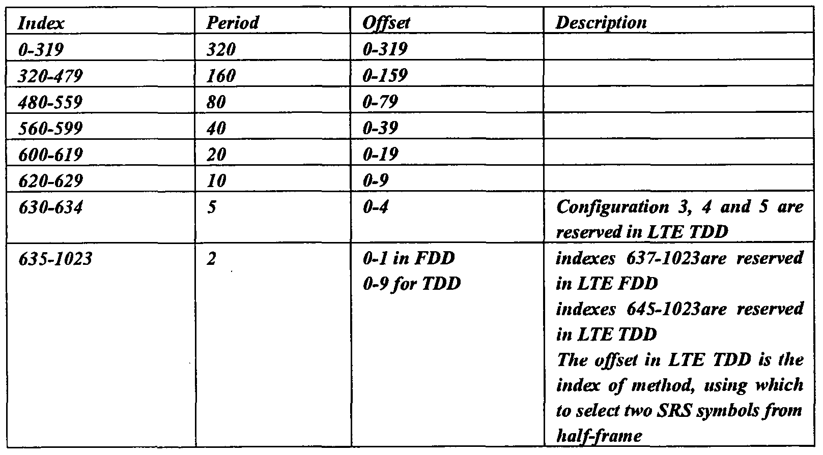
For the LTE FDD system, since the maximum period of SRS is among {2, 5 , 10, 20, 40, 80, 160, 320} ms, in order to achieve a maximum flexibility, for an arbitrary period, a possible SRS offset is select from {0, 1 , ... , Period-1 }. Therefore, for the LTE FDD, the SRS of the designated user includes 2+5+10+20+40+80+160+320=637 indexes. This method provides a maximum flexibility, and needs 10 bits to present 637 indexes. Since 1024 pieces of information may be indicated by 10 bits, the other 1024-637=387 indexes are reserved for various purpose.
When the period is 320ms, providing at most 320 offsets is unnecessary, the 10 bits may be not the most reasonable. In this condition, the number of indexes can decrease with the decrease of the offset range, so that a total number of bits needed decreases and the number of reserved indexes decreases.
UE receives an index N indicating a period of SRS transmission from base station For a LTE TDD system, the period value of SRS is also among (2, 5, 10, 20, 40, 80, 160, 320} ms, the design of offset is the same as in LTE FDD except that when the period is 2ms and 5ms. However compared with LTE FDD the difference is that in LTE TDD, the uplink sub-frame isn't always continuous, so that there doesn't have a complete period of 2ms. For this reason, the period of 2ms for LTE should have some special design. Currently, there are seven uplink and downlink configurations supported in LTE TDD, illustrated in figure 5(501-507). A group of corresponding SRS indexes is defined to indicate the SRS index of designated user of 2ms period. For configuration of 0(501), 1(502), 2(503) and 6(507), all of the indexes indicate that in a 5 ms half-frame period or 5 ms frame period, two continuous or arbitrary OFDM positions in logical from the OFDM symbols which are configured to transmit SRS are selected, and the designated user is indicated to use this position to transmit SRS. For configuration of 3(504), 4(505) and 5(506), all of the indexes indicate that in a 10ms frame period, two continuous or arbitrary OFDM positions in logical from the OFDM symbols which are configured to transmit SRS are selected, and the designated user is indicated to use this position to transmit SRS. The definition mentioned is used to inform the designated user that how to select the OFDM position used for SRS transmission in the 2ms period.
Considering that in LTE TDD system, there are at most 5 OFDM symbols used to transmit SRS in 5ms half-frame, which include two symbols in UpPTS, and three OFDM symbols in uplink sub-frame 2, 3 and 4. Thus, if the two selected symbols are arbitrary, the number of choice is C(5,2)=10 (C presents for combination) with 10 corresponding indexes. Ten indexes need to correspond with the concrete OFDM symbols. Any correspondence will be used without departing from the spirit and scope of the present invention. For example the correspondence may be selected randomly, or when making correspondence, assigning the indexes with high priority to a former or latter position. One consideration about priority is considering a situation with 1 or 2 UpPTS symbol first. There are four situations (a last OFDM symbol and a first OFDM symbol isn't logically continuous) or five situations (a last OFDM symbol and a first OFDM symbol is logically continuous) if select two continuous OFDM symbols, so that four or five indexes are needed for indicating.
If the period is 5ms, a special case in LTE TDD is that, for configuration 3(504), 4(505) and 5(506), there is no uplink resource in the second half-frame in 10ms frame. So that SRS can't be transmitted in the second half-frame. If the two continuous or arbitrary OFDM positions in logical are selected from the OFDM symbols configured to transmit SRS in the first half-frame, the definition is the same as in LTE TDD with 2ms period. Therefore, in order to simplify the system design, 5ms period isn't suitable for configurations, 4 and 5 in LTE TDD in present invention.
Compared with LTE FDD, in some situation, period of 2ms and 5ms aren't supported, so that the period of 2ms and 5ms is redefined to achieve a similar function as in LTE FDD.
Based on the redefined method to redefine the 2ms period of configuration 0 to 2 and 6, an actual period is 5ms, that is, two SRS symbols are occupied every 5ms. In order to redefine the 2ms period of configuration 3 to 5, the actual period is 10ms, that is, two SRS symbols are occupied every lOrns. In fact, the redefinition described above for 2ms and 5ms period for LTE TDD can be used in system configuration and makes the comparison with LTE FDD easy. Sometimes, the system doesn't support the period of 2ms and 5ms, and directly define to configure two SRS in 5ms or 10ms. The essence of these two methods is the same. The essence of the method is the same as the redefinition of period. More specifically for the second method, SRS period of 2ms isn't supported in LTE TDD. For configuration 3 to 5, SRS period of 5ms isn't supported. However, two SRS symbols can be configured every half- frame (every 5ms), such as for configuration 0 to 2 and 6. Also, two SRS symbols can be configured in the first half-frame (every 10ms) in radio frame, such as for configuration 3 to 5. The configuration of two SRS symbols in every half-frame can use a similar method compared with the method used in the redefinition of 2ms and 5ms period described above, so to speak, a completely flexible configuration needs to indicate C(5,2)=10 choices, or decrease the number of selection by restrict the method of configuration, the invention is not limited.
Furthermore, the redefinition of 2ms period described above is to configure two SRS symbols in a half-frame(5ms), that is, it is reasonable to define that 2ms period isn't support in LTE TDD system and two SRS symbols is configured every half-frame (5ms). For configuration 0 to 2 and 6, the actual period is 5ms, that's to say that, two SRS symbols are occupied every 5ms. For configuration 3 to 5, the actual period is 10ms, that's to say that, two SRS symbols are occupied every 10ms. The configuration of two SRS symbols in every half-frame can use a similar method compared with the method used in the redefinition of 2ms and 5ms period described above, that is, a flexible configuration needs to indicate C(5,2)=10 choices, or decrease the number of selection by limiting the method of configuration, the invention is not limited.
After the UE receives information N indicating SRS transmission from the network, when the SRS period indicated by N is less than or equal to the number of OFDM symbols configured to transmit SRS in the entire cell in a period, the offset can be calculated as follows:
If the range of N is from 0 to 320/f-l, the period indicated by N is 320ms, then the SRS is transmitted by using offset N*f.
If the range of N is from 320/f to 320/f+160/m-l, the period indicated by N is 160ms, then the SRS is transmitted by using offset N-320/fm.
If the range of N is from 320/f+160/m to 320/f+160/m+80/t-l, the period indicated by N is 80ms, then the SRS is transmitted by using offset N-320/f-160/m*t. If the range of N is from 320/f+160/m+80/t to 320/f+160/m+80/t+40/n-l, the period indicated by N is 40ms, then the SRS is transmitted by using offset N-320/f-160/m-80/t*n.
If the range of N is from 320/f+160/m+80/t+40/n to 320/f+160/m+80/t+40/n+20/p-l, the period indicated by N is 20ms, then the SRS is transmitted by using offset N-320/f-160/m-80/t-40/n*p.
If the range of N is from 320/f+160/m+80/t+40/n+20/p to 320/f+160/m+80/t+40/n+20/p+10/x-l, the period indicated by N is 10ms, then the SRS is transmitted by using offset N-320/f-160/m-80/t-40/n-20/p*x. If the range of N is from 320/f+160/m+80/t+40/n+20/p+10/x to
320/f+160/m+80/t+40/n+20/p+10/x+5-l, the period indicated by N is 10ms, then the SRS is transmitted by using offset N-320/f- 160/m-80/t-40/n-20/p- 10/x.
Where f, m, t, n can be 1, 2,4, 8; p can be 1, 2, 4, 5, 10; x can be 1, 2, 5; M presents, a number of OFDM symbol configured to transmit SRS in a period in the whole cell indicated by information N. The value of f, m, t, n and M need to be set statically in system specification. "-" is a symbol for subtraction.
After UE receives the information N indicating the SRS transmission from network, when the SRS period indicated by N is greater than the number of OFDM symbols configured to transmit SRS in the entire cell in a period, the offset can be calculated as follows:
If the range of N is from 0 to M-I, the period indicated by N is 320ms, then the SRS is transmitted by using offset N;
Reserved by the system if the range of N is from M to 320/f-l ;
If the range of N is from 320/f to 320/f+M-l, the period indicated by N is
160ms, then the SRS is transmitted by using offset N-320/f; Reserved by the system if the range of N is from M to 320/f+160/m-l;
If the range of N is from 320/f+160/m to M-I, the period indicated by N is 80ms, then the SRS is transmitted by using offset N-320/f- 160/m; Reserved by the system if the range of N is from M to 320/f+l 60/m+80/t-l;
If the range of N is from 320/f+160/m+80/t to M-I, the period indicated by N is 40ms, then the SRS is transmitted by using offset N-320/f-160/m-80/t;
Reserved by the system if the range of N is from M to 5 320/f+l 60/m+80/t+40/n-l ;
If the range of N is from 320/f+l 60/m+80/t+40/n to M-I, the period indicated by N is 20ms, then the SRS is transmitted by using offset
N-320/f-160/m-80/t-40/n;
Reserved by the system if the range of N is from M to i o 320/f+ 160/m+80/t+40/n+20/p- 1 ;
If the range of N is from 320/f+l 60/m+80/t+40/n+20/p to M-I, the period indicated by N is 10ms, then the SRS is transmitted by using offset
N-320/f- 160/m-80/t-40/n-20/p;
Reserved by the system if the range of N is from M to 15 320/f+l 60/m+80/t+40/n+20/p+10/x-l ;
If the range of N is from 320/f+160/m+80/t+40/n+20/p+10/x to M-I, the period indicated by N is 5 ms, then the SRS is transmitted by using offset
N-320/f-160/m-80/t-40/n-20/p-10/x;
Reserved if the range of N is from M to 20 320/f+160/m+80/t+40/n+20/p+10/x+5-l .
Where f, m, t, n can be 1, 2,4, 8; p can be 1, 2, 4, 5, 10; x can be 1, 2, 5; M presents the number of OFDM symbol configured to transmit SRS in a period in the whole cell indicated by the information N. The value of f, m, t, n and M need to be set statically in system specification. "-" is a symbol for subtraction. 25 The design method described above is the most basic SRS design for the designated user. The invention considers the coherence of signal format in
LTE FDD and LTE TDD, the detailed principle is as follows: firstly, the - information bits indicating the SRS transmission of designated user in LTE
FDD and LTE TDD is the same. For example, 10 bits or 9 bits are used to inform. Next, the reserved index occupies and only occupies one section of continuous indexes both in LTE FDD and LTE TDD.
According to the design principle of LTE TDD compatible with of LTE FDD, the SRS transmission signal for designated user can refer to a table below:
Figure imgf000013_0001
Table 1 Indexes of SRS signal
Follow table is used to describe by using the same design principle:
Figure imgf000013_0002
Table 2 Indexes of SRS signal
Considering the period value could be ordered from small to large, a table uniformly describing the indexes of SRS signal for LTE TDD and LTE FDD could be obtained:
Figure imgf000014_0001
Table 3 Indexes of SRS signal
In order to ensure a coherence of design for LTE FDD and LTE TDD, a degree of flexibility may be sacrificed in LTE TDD. If period is 2ms, the number of indexes is limited to 2 in LTE TDD, so that the number of indexes in LTE FDD and LTE TDD is exactly the same. This is shown in Table 4:
Figure imgf000014_0002
Table 4 Indexes of SRS signal In the above method, considering the coherence for LTE FDD and LTE TDD, the configuration in both systems should keep the same. The detailed method for LTE TDD is optimized. If using different table for LTE FDD and LTE TDD is allowed, table 1 to 4 could just used in LTE TDD, and another design for LTE FDD is achievable. The mainly difference is that in LTE FDD, only two indexes are occupied in 2ms period.
The above description is the SRS configuration method based on the redefinition of 2ms and 5ms period in LTE TDD. For redefinition of the 2ms period of configuration 0 to 2 and 6, the actual period is 5ms. For redefinition of the 2ms period of configuration 3 to 5, the actually period is 10ms. So that when using the period value of SRS for calculation, for the 2ms period of configuration 0 to 2 and 6, 5ms is used as the period, and for the 2ms period of configuration 3 to 5, 10ms is used as the period. If the redefinition of 2ms and 5ms period in LTE TDD is not used, in some situation without supporting 2ms and 5ms period, the system defines that two SRS is configured in 5ms or 10ms. When using the period of SRS, the value of period is used to calculate directly. Table 5 and table 6 are two possible detailed configuration methods. The period value in table 5 or table 6 is an actual period value. It is assumed that all of C (5 ,2)= 10 methods of selecting two SRS symbols in half-frame are supported.
In table 5, when the index is between 0 and 9, two SRS are configured in a period of 5ms. The corresponding offset 0 to 9 is the indexes for the methods for selecting two SRS symbols from half-frame substantially. When the index is between 10 and 14, one SRS is configured in a period of 5 ms, and the offset presents a position of assigned SRS. When the index is between 15 and 24, two SRS are configured in a period of 10ms. The corresponding offset 0 to 9 is the index for the methods for selecting two SRS symbols from half-frame substantially. When the index is between 25 and 34, one SRS is configured in a period of 10ms, and the offset presents the position of assigned SRS.
Figure imgf000016_0001
Table 5 Indexes of SRS signal
Table 6 has the same effect as that of Table 5 except for an order of rows to implement a new embodiment. The invention is limited to the order of SRS period in the table.
In table 6, when the index is between 0 and 9, two SRS are configured in a period of 5 ms. The corresponding offset 0 to 9 is the index of the methods, for selecting two SRS symbols from half-frame substantially. When the index is between 10 and 19, two SRS are configured in a period of 10ms. The corresponding offset 0 to 9 is the index of the methods for selecting two SRS symbols from half-frame substantially. When the index is between 20 and 24, one SRS is configured in a period of 5ms, and the offset presents the position of assigned SRS. When the index is between 25 and 34, one SRS is configured in a period of 10ms, and the offset value presents the position of assigned SRS.
Figure imgf000016_0002
Figure imgf000017_0001
Table 6 Indexes of SRS signal
If the redefinition of 2ms and 5ms period in LTE TDD is not used, the period of 2ms not supported in LTE TDD is defined and two SRS are configured every half-frame (5ms). So that, when using the period value of SRS for calculating, for configuration 0 to 2 and 6, 5ms is used as the period, for configuration 3 to 5, 10ms is used as the period. Table 6 is a possible configuration method. It is assumed that all the C(5,2)=10 methods used to select two SRS symbols in half-frame are supported.
In table 7, when the index is between 0 and 9, two SRS are configured in a period of 5ms. The corresponding offset 0 to 9 is the index of the methods for selecting two SRS symbols from half-frame. When the index is between 10 and 14, one SRS is configured in a period of 5ms, and the offset indicates the position of the assigned SRS. When the index is between 15 and 24, one SRS is configured in a period of 10ms, and the offset presents the position of assigned SRS.
Figure imgf000017_0002
Table 7 Indexes of SRS signal C(5,2)=10 indexes are used to achieve complete flexibility for transmitting two SRS in a period. A mapping method from the indexes to two selected SRS symbol is as follows: when UpPTS includes two SRS symbols, a first SRS symbol is indicated by SRS sub-frame offset 0 and a second SRS symbol is indicated by SRS sub-frame offset 1. When UpPTS includes one SRS symbol, the SRS symbol is indicated by SRS sub-frame offset 1. The SRS symbol in the other sub-frame is indicted by the corresponding offset (that is, 2, 3 or 4) . Therefore, a possible mapping method from C(5,2)=10 indexes to two selected SRS symbols is shown as follows:
Figure imgf000018_0001
Table 8 Mapping from 10 indexes to two selected SRS symbols
The network uses RRC signal to transmit the SRS signal generated in step 1.
The generated SRS information is mapped to transmission channel and physical channel, then transmitted to UE through the antenna after being processed accordingly.
An apparatus for transmitting SRS of designated user is illustrated in figure 3. The apparatus includes a SRS generator module (301) for generating the SRS information. The SRS information is mapped to a transmission channel module (302), passed to a physical channel mapping module (303), and the SRS of designated user is transmitted through the antenna (304).
The apparatus for transmitting the SRS in LTE UE is illustrated in figure
4. The apparatus includes a module (401) which generates an SRS sequence based on the SRS information of designated user received by a module (402) and the other information (such as the cycle offset used to transmit SRS, comb, the bandwidth and so on) received by a module (403). Under the control of a module (404), the power is adjusted by a module (405) in the physical resource allocated at a proper timing and the SRS of designated user is transmitted by using an antenna module (407).
Two examples according to present invention are described as follows. In order to avoid making the description ambiguous, detailed descriptions for known functions are omitted.
A First Example
Configuration 1(602) in LTE TDD is applied in this example. The signal information indicating the SRS transmission of designated user is generated by the LTE network. According to the table 1, the index 635 is selected. For LTE TDD, the index means the period is 2ms, indicating that the designated user transmits SRS in the first and second symbol in UpPTS (601 or 604). For LTE FDD, the index means that the designated user may use the available OFDM symbol in the first sub-frame in the 2ms frame to transmit SRS. Then, via the transmission channel mapping and physical channel mapping, the system transmits the index information to the designated user.
A Second Example
Configuration 3(704) in LTE TDD is applied in this example. The signal information indicating the SRS transmission of designated user is generated by the LTE network. According to the table 1, the index 637 which indicates that the period is 2ms is selected. For LTE TDD, the index means that the designated user transmits SRS in the first symbol (701) and the first normal uplink sub-frame (sub-frame 2) (702). For LTE FDD, the index is reserved by the system and the system doesn't use the index to transmit SRS information of designated user. Then, after the transmission channel mapping and physical channel mapping, the system transmit s the index information to the designated user.
While the invention has been shown and described with reference to certain exemplary embodiments of the present invention thereof, it will be understood by those skilled in the art that various changes in form and details may be made therein without departing from the spirit and scope of the present invention as defined by the appended claims and their equivalents.

Claims

WHAT IS CLAIMED IS:
1. A method for transmitting an uplink SRS, comprising steps of: a) UE receives the information related to period and offset for SRS transmission; b) UE generates SRS sequence;; and c) If above said information indicates SRS period is 2ms, UE transmits SRS in 2 SCFDMA symbols in a half frame..
2. The method according to Claim 1, further comprising step of: If above said information indicates SRS period is not 2ms, UE transmits
SRS with the indicated SRS period and offset.
3. A method for transmitting an uplink SRS by an LTE UE comprising steps of: a) the UE receiving information N indicating SRS transmission; b) generating a SRS sequence by the UE; c) transmitting the SRS in case of occupying one or two OFDM symbols every period based on a period indicated by information N.
4. The method according to Claim 3, wherein in step c), the SRS is transmitted over two symbols in 5ms period.
5. The method according to Claim 3, wherein in step c): the SRS is transmitted over two symbols in 10ms period.
PCT/KR2009/000050 2008-02-05 2009-01-07 Method and apparatus for transmitting srs in lte tdd system WO2009099273A1 (en)

Priority Applications (13)

Application Number Priority Date Filing Date Title
EP09708920.5A EP2241027B1 (en) 2008-02-05 2009-01-07 Method and apparatus for transmitting srs in lte tdd system
US12/865,334 US8520492B2 (en) 2008-02-05 2009-01-07 Method and apparatus for transmitting SRS in LTE TDD system
US14/011,346 US9025429B2 (en) 2008-02-05 2013-08-27 Method and apparatus for transmitting SRS in LTE TDD system
US14/625,263 US9160505B2 (en) 2008-02-05 2015-02-18 Method and apparatus for transmitting SRS in LTE TDD system
US14/625,253 US9166757B2 (en) 2008-02-05 2015-02-18 Method and apparatus for transmitting SRS in LTE TDD system
US14/625,268 US9160506B2 (en) 2008-02-05 2015-02-18 Method and apparatus for transmitting SRS in LTE TDD system
US14/625,290 US9160509B2 (en) 2008-02-05 2015-02-18 Method and apparatus for transmitting SRS in LTE TDD system
US14/625,285 US9160508B2 (en) 2008-02-05 2015-02-18 Method and apparatus for transmitting SRS in LTE TDD system
US14/625,278 US9160507B2 (en) 2008-02-05 2015-02-18 Method and apparatus for transmitting SRS in LTE TDD system
US14/625,243 US9166756B2 (en) 2008-02-05 2015-02-18 Method and apparatus for transmitting SRS in LTE TDD system
US14/625,298 US9160510B2 (en) 2008-02-05 2015-02-18 Method and apparatus for transmitting SRS in LTE TDD system
US14/866,101 US9413504B2 (en) 2008-02-05 2015-09-25 Method and apparatus for transmitting SRS in LTE TDD system
US14/866,130 US9413505B2 (en) 2008-02-05 2015-09-25 Method and apparatus for transmitting SRS in LTE TDD system

Applications Claiming Priority (2)

Application Number Priority Date Filing Date Title
CN200810004863.0 2008-02-05
CN200810004863.0A CN101505485B (en) 2008-02-05 2008-02-05 Method and apparatus for sending SRS in LTE TDD system

Related Child Applications (2)

Application Number Title Priority Date Filing Date
US12/865,334 A-371-Of-International US8520492B2 (en) 2008-02-05 2009-01-07 Method and apparatus for transmitting SRS in LTE TDD system
US14/011,346 Continuation US9025429B2 (en) 2008-02-05 2013-08-27 Method and apparatus for transmitting SRS in LTE TDD system

Publications (1)

Publication Number Publication Date
WO2009099273A1 true WO2009099273A1 (en) 2009-08-13

Family

ID=40952323

Family Applications (1)

Application Number Title Priority Date Filing Date
PCT/KR2009/000050 WO2009099273A1 (en) 2008-02-05 2009-01-07 Method and apparatus for transmitting srs in lte tdd system

Country Status (5)

Country Link
US (12) US8520492B2 (en)
EP (1) EP2241027B1 (en)
KR (1) KR101554584B1 (en)
CN (1) CN101505485B (en)
WO (1) WO2009099273A1 (en)

Cited By (2)

* Cited by examiner, † Cited by third party
Publication number Priority date Publication date Assignee Title
EP2139151A2 (en) * 2008-06-25 2009-12-30 Samsung Electronics Co., Ltd. Method for transmitting a sounding reference signal in a LTE TDD system
US10979868B2 (en) 2016-04-01 2021-04-13 Huawei Technologies Co., Ltd. Method, user equipment, and base station for transmitting uplink signal based on carrier and subframe indication information

Families Citing this family (38)

* Cited by examiner, † Cited by third party
Publication number Priority date Publication date Assignee Title
CN101677458A (en) * 2008-03-26 2010-03-24 三星电子株式会社 Method for sending SRS in LTE TDD system and device thereof
KR101709499B1 (en) * 2009-03-25 2017-02-23 엘지전자 주식회사 Method for transmitting sounding reference signal in wireless communication system and apparatus therefor
CN101848541B (en) * 2009-03-27 2013-03-13 电信科学技术研究院 Method and device for sending sounding reference signal
CN105049165B (en) * 2009-11-02 2019-09-10 诺基亚通信公司 Method and apparatus for telecommunications
KR20110051969A (en) * 2009-11-11 2011-05-18 주식회사 팬택 Method and apparatus for transmission of reference signal and information for reference signal in coordinated multi-point transmission/reception system
CN102104877B (en) * 2009-12-17 2014-11-05 中国移动通信集团设计院有限公司 Carrier allocating method and system in TD-SCDMA (time division-synchronous code division multiple access) system
CN101795145B (en) * 2010-02-08 2014-11-05 中兴通讯股份有限公司 Sending method and system for measuring reference signals
US9055535B2 (en) 2010-04-30 2015-06-09 Panasonic Intellectual Property Corporation Of America Wireless communication device and method for controlling transmission power
JP5718597B2 (en) * 2010-08-06 2015-05-13 京セラ株式会社 Wireless base station, wireless terminal, and wireless communication method
CN102404074B (en) * 2010-09-17 2014-06-18 电信科学技术研究院 Transmission method and equipment of non-periodic SRS (Stimulated Raman scattering) in TDD (Time Division Duplexing) system
CN102076026B (en) * 2011-01-06 2013-06-05 大唐移动通信设备有限公司 Sounding reference signal transmitting method, device and terminal
KR20130018073A (en) * 2011-08-12 2013-02-20 주식회사 팬택 Srs transmission control method of transmission point, transmission point thereof, srs transmission method of user equipment, and user equipment thereof
US9060343B2 (en) 2011-10-03 2015-06-16 Mediatek, Inc. Support of network based positioning by sounding reference signal
JP5783062B2 (en) * 2012-01-24 2015-09-24 富士通株式会社 Wireless device, wireless control method, and wireless control program
US9351288B2 (en) * 2012-06-05 2016-05-24 Samsung Electronics Co., Ltd. Uplink channel sounding and channel state information estimation in mobile communication systems with multiple antennas
CN103873394B (en) * 2012-12-13 2017-08-25 上海贝尔股份有限公司 A kind of method and apparatus for being used to carry out offset estimation based on TDD special subframes
CN105027657B (en) * 2013-03-05 2018-12-11 夏普株式会社 Terminal installation, base station apparatus, integrated circuit and wireless communications method
WO2014156894A1 (en) * 2013-03-27 2014-10-02 シャープ株式会社 Terminal device, base station device, communications method, and integrated circuit
CN104469926B (en) * 2013-09-16 2019-03-12 上海朗帛通信技术有限公司 Transmission method and device in a kind of D2D system
EP3099119B1 (en) * 2014-01-24 2018-09-19 LG Electronics Inc. Method for controlling transmission power of sounding reference signal on special subframe in tdd-type wireless communication system and device therefor
US9420584B2 (en) 2014-09-17 2016-08-16 Telefonaktiebolaget Lm Ericsson (Publ) Uplink sounding reference signals for machine type communications (MTC) user equipment (UE)
CN111770038A (en) * 2014-12-16 2020-10-13 富士通株式会社 Downlink channel estimation method, device, communication system and terminal
WO2016115548A1 (en) * 2015-01-16 2016-07-21 Ping Liang Enhanced srs for massive mimo channel estimation
CN106664193B (en) * 2015-04-10 2020-12-29 Lg电子株式会社 Method and apparatus for transmitting or receiving sounding reference signal in wireless communication system
US10298281B2 (en) * 2015-05-07 2019-05-21 Nxp B. V. Establishing communication with wireless devices using orientation data
CN106685616B (en) 2015-11-06 2020-10-13 中兴通讯股份有限公司 Sending method and device of Sounding Reference Signal (SRS)
CN106982110B (en) * 2016-01-15 2020-04-14 上海诺基亚贝尔股份有限公司 Method and apparatus for NB-IoT transmission frame configuration using LTE TDD frame structure
CN106788927B (en) * 2016-05-13 2019-09-17 北京展讯高科通信技术有限公司 The sending method and device of SRS
US10608856B2 (en) * 2016-06-16 2020-03-31 Samsung Electronics Co., Ltd. Transmission of reference signals in a communication system
JP6891419B2 (en) * 2016-07-29 2021-06-18 ソニーグループ株式会社 Terminal equipment, base stations, methods and recording media
CN109891737B (en) 2016-10-31 2022-04-01 三菱电机株式会社 Motor driving device
WO2018082060A1 (en) * 2016-11-04 2018-05-11 华为技术有限公司 Method for processing sounding reference signal, and base station and user equipment
US10218424B2 (en) 2017-01-13 2019-02-26 Nokia Technologies Oy Reference signal indications for massive MIMO networks
CN113660188A (en) 2017-11-17 2021-11-16 华为技术有限公司 Method and device for transmitting Sounding Reference Signal (SRS)
AU2018407157A1 (en) * 2018-02-08 2020-06-25 Guangdong Oppo Mobile Telecommunications Corp., Ltd. Method for transmitting information, method for receiving information, terminal device, and network device
CN108768599B (en) * 2018-04-02 2022-08-19 中兴通讯股份有限公司 Method and device for sending and receiving uplink signal, storage medium and electronic equipment
CN112787779B (en) * 2019-11-07 2022-10-04 华为技术有限公司 Communication method and user equipment
WO2023228370A1 (en) * 2022-05-26 2023-11-30 株式会社Nttドコモ Terminal, wireless communication method, and base station

Citations (2)

* Cited by examiner, † Cited by third party
Publication number Priority date Publication date Assignee Title
EP1471666A2 (en) * 2003-04-23 2004-10-27 Lg Electronics Inc. Channel synchronization apparatus of TDD-based mobile communication terminal
US20070104164A1 (en) * 2004-10-14 2007-05-10 Rajiv Laroia Methods and apparatus for determining, communicating and using information including loading factors which can be used for interference control purposes

Family Cites Families (18)

* Cited by examiner, † Cited by third party
Publication number Priority date Publication date Assignee Title
JP2004032679A (en) 2002-02-28 2004-01-29 Matsushita Electric Ind Co Ltd Communication apparatus and communication system
US7738901B2 (en) * 2003-07-10 2010-06-15 Telefonaktiebolaget Lm Ericsson (Publ) Secondary link power control in a wireless communication network
US8417248B2 (en) * 2006-08-14 2013-04-09 Texas Instruments Incorporated Methods and apparatus to schedule uplink transmissions in wireless communication systems
US7957759B2 (en) * 2006-12-08 2011-06-07 Texas Instruments Incorporated Wideband reference signal transmission in SC-FDMA communication systems
US8498639B2 (en) * 2007-02-09 2013-07-30 Qualcomm Incorporated Flexible channel quality indicator reporting
US8102809B2 (en) * 2007-06-19 2012-01-24 Texas Instruments Incorporated Time-sharing of sounding resources
US8055301B2 (en) * 2007-08-06 2011-11-08 Mitsubishi Electric Research Laboratories, Inc. Wireless networks incorporating implicit antenna selection based on received sounding reference signals
US9131534B2 (en) * 2007-08-08 2015-09-08 Telefonaktiebolaget L M Ericsson (Publ) Method and apparatus for configuring sounding signals in a wireless communication network
PL2176999T3 (en) * 2007-08-08 2018-01-31 Ericsson Telefon Ab L M Sounding using different sounding configurations
US8798183B2 (en) * 2007-08-13 2014-08-05 Qualcomm Incorporated Feedback and rate adaptation for MIMO transmission in a time division duplexed (TDD) communication system
US8503375B2 (en) * 2007-08-13 2013-08-06 Qualcomm Incorporated Coding and multiplexing of control information in a wireless communication system
US8014265B2 (en) * 2007-08-15 2011-09-06 Qualcomm Incorporated Eigen-beamforming for wireless communication systems
US8681666B2 (en) * 2007-10-01 2014-03-25 Qualcomm Incorporated Partial discarding of cyclic prefix for efficient TDD or half-duplex FDD operation
US8780790B2 (en) * 2008-01-07 2014-07-15 Qualcomm Incorporated TDD operation in wireless communication systems
US9001791B2 (en) * 2008-01-31 2015-04-07 Telefonaktiebolaget L M Ericsson (Publ) Detection of time division duplex downlink/uplink configuration
CN101615928B (en) 2008-06-25 2016-05-18 三星电子株式会社 The method and apparatus of transmitting SRS signaling in LTE system
CN101651469B (en) 2008-08-15 2013-07-24 三星电子株式会社 Frequency hopping method for sending uplink monitoring reference mark in LET system
CN101378290B (en) * 2008-09-23 2013-02-27 中兴通讯股份有限公司 Control method and apparatus signal transmission

Patent Citations (2)

* Cited by examiner, † Cited by third party
Publication number Priority date Publication date Assignee Title
EP1471666A2 (en) * 2003-04-23 2004-10-27 Lg Electronics Inc. Channel synchronization apparatus of TDD-based mobile communication terminal
US20070104164A1 (en) * 2004-10-14 2007-05-10 Rajiv Laroia Methods and apparatus for determining, communicating and using information including loading factors which can be used for interference control purposes

Non-Patent Citations (1)

* Cited by examiner, † Cited by third party
Title
See also references of EP2241027A4 *

Cited By (8)

* Cited by examiner, † Cited by third party
Publication number Priority date Publication date Assignee Title
EP2139151A2 (en) * 2008-06-25 2009-12-30 Samsung Electronics Co., Ltd. Method for transmitting a sounding reference signal in a LTE TDD system
EP2139151A3 (en) * 2008-06-25 2012-05-23 Samsung Electronics Co., Ltd. Method for transmitting a sounding reference signal in a LTE TDD system
US8259700B2 (en) 2008-06-25 2012-09-04 Samsung Electronics Co., Ltd Method for transmitting a sounding reference signal in a LTE TDD system
EP2720400A1 (en) * 2008-06-25 2014-04-16 Samsung Electronics Co., Ltd Method for transmitting a sounding reference signal in a LTE TDD system
US9787447B2 (en) 2008-06-25 2017-10-10 Samsung Electronics Co., Ltd. Method for transmitting a sounding reference signal in a LTE TDD system
US10411855B2 (en) 2008-06-25 2019-09-10 Samsung Electronics Co., Ltd Method for transmitting a sounding reference signal in an LTE TDD system
US10979868B2 (en) 2016-04-01 2021-04-13 Huawei Technologies Co., Ltd. Method, user equipment, and base station for transmitting uplink signal based on carrier and subframe indication information
US11622246B2 (en) 2016-04-01 2023-04-04 Huawei Technologies Co., Ltd. Methods and apparatus for communication an uplink signaling in a target subframe

Also Published As

Publication number Publication date
CN101505485B (en) 2014-11-05
US9413505B2 (en) 2016-08-09
EP2241027B1 (en) 2019-05-08
US20150163033A1 (en) 2015-06-11
US9160509B2 (en) 2015-10-13
US20160020880A1 (en) 2016-01-21
EP2241027A1 (en) 2010-10-20
US9166757B2 (en) 2015-10-20
US9160507B2 (en) 2015-10-13
US20100309852A1 (en) 2010-12-09
US9160506B2 (en) 2015-10-13
US9160508B2 (en) 2015-10-13
US9160505B2 (en) 2015-10-13
EP2241027A4 (en) 2016-03-23
US20150163786A1 (en) 2015-06-11
US20150163803A1 (en) 2015-06-11
US9413504B2 (en) 2016-08-09
US20150163785A1 (en) 2015-06-11
US9166756B2 (en) 2015-10-20
US9160510B2 (en) 2015-10-13
US9025429B2 (en) 2015-05-05
US20130343359A1 (en) 2013-12-26
US20150163035A1 (en) 2015-06-11
US20150163031A1 (en) 2015-06-11
US20150163032A1 (en) 2015-06-11
CN101505485A (en) 2009-08-12
US8520492B2 (en) 2013-08-27
KR20100114882A (en) 2010-10-26
US20150163034A1 (en) 2015-06-11
US20160013924A1 (en) 2016-01-14
KR101554584B1 (en) 2015-09-21

Similar Documents

Publication Publication Date Title
EP2241027B1 (en) Method and apparatus for transmitting srs in lte tdd system
EP2139151B1 (en) Method for transmitting a sounding reference signal in a LTE TDD system
CN106063353B (en) System and method for OFDM with flexible subcarrier spacing and symbol duration
KR20190044691A (en) Method and apparatus for transmitting an initial access signal in a wireless communication system
WO2009132178A2 (en) Backward compatible bandwidth extension
KR20190003758A (en) Method for transmitting and receiving information, user equipment and base station
KR20120000482A (en) Method and apparatus for transmitting and receiving resource allocation and periodicity information for transmission of aperiodic sounding reference signal
KR20170049379A (en) Method and apparatus for configuring synchronization signal for narrowband wireless communication cellular system and method and apparatus for transmitting the synchronization signal

Legal Events

Date Code Title Description
121 Ep: the epo has been informed by wipo that ep was designated in this application

Ref document number: 09708920

Country of ref document: EP

Kind code of ref document: A1

ENP Entry into the national phase

Ref document number: 20107015097

Country of ref document: KR

Kind code of ref document: A

WWE Wipo information: entry into national phase

Ref document number: 2009708920

Country of ref document: EP

WWE Wipo information: entry into national phase

Ref document number: 12865334

Country of ref document: US

NENP Non-entry into the national phase

Ref country code: DE