WO2013021552A1 - Positioning server device and positioning control method - Google Patents

Positioning server device and positioning control method Download PDF

Info

Publication number
WO2013021552A1
WO2013021552A1 PCT/JP2012/004620 JP2012004620W WO2013021552A1 WO 2013021552 A1 WO2013021552 A1 WO 2013021552A1 JP 2012004620 W JP2012004620 W JP 2012004620W WO 2013021552 A1 WO2013021552 A1 WO 2013021552A1
Authority
WO
WIPO (PCT)
Prior art keywords
positioning
range
client
unit
fingerprint
Prior art date
Application number
PCT/JP2012/004620
Other languages
French (fr)
Japanese (ja)
Inventor
斉藤 佳子
池田 新吉
中尾 正悟
Original Assignee
パナソニック株式会社
Priority date (The priority date is an assumption and is not a legal conclusion. Google has not performed a legal analysis and makes no representation as to the accuracy of the date listed.)
Filing date
Publication date
Application filed by パナソニック株式会社 filed Critical パナソニック株式会社
Priority to JP2013527853A priority Critical patent/JP5974005B2/en
Priority to EP12821781.7A priority patent/EP2741099B1/en
Priority to US14/235,732 priority patent/US9037189B2/en
Publication of WO2013021552A1 publication Critical patent/WO2013021552A1/en

Links

Images

Classifications

    • HELECTRICITY
    • H04ELECTRIC COMMUNICATION TECHNIQUE
    • H04WWIRELESS COMMUNICATION NETWORKS
    • H04W4/00Services specially adapted for wireless communication networks; Facilities therefor
    • H04W4/02Services making use of location information
    • H04W4/021Services related to particular areas, e.g. point of interest [POI] services, venue services or geofences
    • GPHYSICS
    • G01MEASURING; TESTING
    • G01SRADIO DIRECTION-FINDING; RADIO NAVIGATION; DETERMINING DISTANCE OR VELOCITY BY USE OF RADIO WAVES; LOCATING OR PRESENCE-DETECTING BY USE OF THE REFLECTION OR RERADIATION OF RADIO WAVES; ANALOGOUS ARRANGEMENTS USING OTHER WAVES
    • G01S5/00Position-fixing by co-ordinating two or more direction or position line determinations; Position-fixing by co-ordinating two or more distance determinations
    • G01S5/02Position-fixing by co-ordinating two or more direction or position line determinations; Position-fixing by co-ordinating two or more distance determinations using radio waves
    • G01S5/0252Radio frequency fingerprinting
    • G01S5/02521Radio frequency fingerprinting using a radio-map
    • G01S5/02524Creating or updating the radio-map
    • G01S5/02525Gathering the radio frequency fingerprints

Definitions

  • the present invention relates to a positioning server device for positioning a client and a positioning control method.
  • the arrival time TOA: Time of Arrival
  • arrival direction AOA: Angle of Arrival
  • received signal strength RSS :
  • TOA Time of Arrival
  • AOA Angle of Arrival
  • RSS received signal strength
  • FIG. 1 shows a general configuration of a positioning method based on received signal strength using WLAN.
  • the system shown in FIG. 1 includes a positioning server SV1 that performs positioning processing, access points AP1 to AP3 (hereinafter referred to as AP) that are connected to the positioning server SV1, and a client CL1 that is connected to the AP.
  • AP access points AP1 to AP3
  • CL1 client CL1
  • the AP transmits a beacon including its own station ID at a predetermined cycle and with a predetermined transmission power.
  • the client CL1 measures the received signal strength (AP1-RSS to AP3-RSS) of the beacon received from the AP (AP1 to AP3), and the ID of the transmission source AP (MAC address, etc.) and the information of the measured received signal strength And is reported to the connected AP or positioning server at a predetermined cycle together with the own station ID.
  • AP received signal strength
  • MAC address MAC address, etc.
  • the AP When the AP receives the AP ID (such as the MAC address) and the received signal strength information from the client CL1, the AP notifies the positioning server SV1 to which the local station is connected in a predetermined cycle.
  • the AP ID such as the MAC address
  • the AP notifies the positioning server SV1 to which the local station is connected in a predetermined cycle.
  • the positioning server SV1 uses the held fingerprint (AP1-fingerprint to AP3-fingerprint) and the received signal strength information (AP1-RSS to AP3-RSS) of the AP reported from the client CL1 to determine the client CL1. Perform positioning. This positioning method will be described in detail subsequently. Then, the positioning result is notified together with the client ID to the AP to which the client CL1 is connected.
  • the AP When the AP receives the client ID and the positioning result from the positioning server SV1, the AP notifies the corresponding client CL1 of the positioning result of the client CL1 connected to the own station. When a plurality of clients are connected, the above series of processing is performed for each client. Note that the positioning server SV1 can directly notify the positioning result to the client CL1.
  • a received signal strength map (hereinafter referred to as a fingerprint) that simulates the propagation environment in the positioning range in advance is created. More specifically, the reception signal strength data measured by the operator at a predetermined positioning range (also referred to as grid position) at a predetermined positioning range is set as the reference received signal strength of the corresponding positioning candidate point of the fingerprint. To do. Alternatively, the received signal strength data at each grid position calculated using a distance attenuation formula such as Friis equation shown in Formula 1 is set as the reference received signal strength of the corresponding positioning candidate point of the fingerprint. For example, a typical value is set for the parameter used in the formula.
  • the positioning unit of the positioning server SV1 specifies the AP and the positioning candidate point, and receives the signal transmitted from the AP at the specified positioning candidate point.
  • the estimated value of the received signal strength at can be obtained. That is, the estimated value of the received signal strength can be extracted from the fingerprint as the reference received signal strength.
  • a plurality of fingerprints AP1-fingerprint to AP3-fingerprint
  • AP1-fingerprint to AP3-fingerprint are created corresponding to the APs (AP1 to AP3) connected to the positioning server SV1 (see FIG. 1).
  • the client CL1 is actually positioned, and further, the fingerprint update process is performed in order to follow the fingerprint in the changing actual propagation environment.
  • Equation 2 a method of estimating a positioning candidate point that minimizes the square error between the fingerprint value and the received signal strength as a positioning result. There are many things based on. That is, for each positioning candidate point, a square error between the reference received signal strength extracted from the fingerprint and the measured received signal strength measured by the client CL1 is calculated, and the positioning candidate point that minimizes this square error is determined as the positioning position. Based on the estimation method.
  • Equation 2 indicates the value of the grid index i that minimizes the value in curly braces.
  • the measured received signal strength at the positioning position measured for the client CL1 corresponds to the fingerprint as if it was a measured received signal strength reflecting the actual propagation environment at that time.
  • the coefficient for determining the fingerprint for example, the path loss coefficient
  • the recalculated path loss coefficient value is reflected in the other positioning candidate points of the fingerprint to receive the signal of the positioning candidate point. Calculate the strength estimate.
  • the recalculated value is registered in the fingerprint as the updated reference received signal strength. That is, the reference received signal strength of the positioning candidate point included in the fingerprint is updated based on the received signal strength actually measured by the client CL1 at one position.
  • the positioning server performs client positioning in a fixed positioning range (for example, a hospital, a museum, a shopping mall, etc.), an error number of about m is conventionally used. Positioning is possible with the positioning accuracy of.
  • a fixed positioning range for example, a hospital, a museum, a shopping mall, etc.
  • the positioning range of the positioning server is usually set so that the movable range of the client targeted by the positioning server (the range in which the client may exist) is almost the same. Is done.
  • the fingerprint received by the positioning server stores reference received signal strength data within the positioning range.
  • the positioning process of the client existing at a position outside the positioning range may be executed by this positioning server.
  • the fingerprint of the positioning server does not correspond to the position of the client outside the positioning range
  • the positioning result includes a large error.
  • the fingerprint is subsequently updated based on the positioning result including the large error, the entire fingerprint includes a large error. For this reason, there arises a problem that the subsequent positioning accuracy is greatly deteriorated.
  • the positioning servers SV1 and SV2 are set to perform positioning in different positioning ranges.
  • the positioning server SV1 mounted on the train car performs positioning using the inside of the train car as a positioning range
  • the platform positioning server SV2 performs positioning using the platform area as a positioning range.
  • the train server positioning server SV1 holds and uses a fingerprint in the train vehicle area as a positioning range
  • the platform positioning server SV2 holds and uses a fingerprint in the platform area as a positioning range.
  • FIGS. 2A and 2B APs connected to the positioning servers SV1 and SV2 are omitted, and one representative is drawn.
  • the client CL1 outside the positioning range (that is, outside the train car area) is provided. Accurate positioning cannot be performed (see FIG. 3A). That is, since the positioning based on Formula 2 is performed, the grid index is limited to the positioning range in the train car.
  • the train car positioning server SV1 updates the fingerprint based on the positioning result greatly deviated. Therefore, a large error is included in the fingerprint. If the fingerprint includes a large error, as shown in FIG. 3B, the positioning accuracy is greatly deteriorated in the subsequent positioning in the train car performed using this fingerprint. For example, the positioning result for the client CL3 ( ⁇ position) in the train car deviates greatly from the position b ( ⁇ position).
  • Such a problem can also occur in the platform positioning server SV2 (see FIG. 2). That is, when the client CL2 connected to the platform AP (AP2) moves from the platform into the train car, a time lag (delay) occurs until the connection is switched to the train car AP (AP1) by handover. During this time, the received signal strength measured in the train car (that is, outside the platform area) may be sent to the platform positioning server SV2. In this case, as in the case of the positioning server SV1 in the above-described train car, erroneous positioning is performed by the platform positioning server SV2, and further, the fingerprint is updated by the erroneous positioning result. Therefore, the positioning accuracy of the subsequent platform with respect to other clients deteriorates.
  • An object of the present invention is to provide a positioning server device and a positioning control method capable of avoiding deterioration in positioning accuracy even when a positioning target client exists at a position outside the normal positioning range as described above. Is to provide.
  • a positioning server device includes an input unit for inputting measurement information of radio waves transmitted between an access point and a client, and radio wave map data (for example, a fingerprint) representing a correspondence relationship between the measurement information and a spatial position. )
  • the radio wave map management unit includes first map data related to a fixed positioning range in which the client to be positioned may exist at normal time, and a specific condition (for example, a specific period or state). The second map regarding the extended positioning range in which the client to be positioned may exist.
  • Pudeta a configuration to manage as the radio map data.
  • the positioning control method includes a step of inputting measurement information of a radio wave transmitted between an access point and a client, the radio wave map data representing a correspondence relationship between the measurement information and the measurement information and a spatial position. And measuring the position of the client based on the measurement information and updating the radio wave map data based on the measurement information and the positioning result of the client.
  • the first map data related to the fixed positioning range in which the client to be positioned may exist, and the possibility that the client to be positioned exists under a specific condition (for example, a specific period or state) occurs.
  • the second map data related to the extended positioning range is included.
  • the radio wave map data is not erroneously updated due to the positioning result including a large error. As a result, subsequent deterioration in positioning accuracy is avoided.
  • the figure explaining the general structure of the positioning method based on the received signal strength using WLAN The figure explaining the conventional example of the positioning range in a railway facility The figure explaining the example of the process which degrades positioning accuracy in a prior art example
  • the figure explaining the correspondence of the variation pattern of the range where the client of positioning object may exist, and fingerprint The figure explaining the effect by the fingerprint of the extended positioning range
  • the figure explaining the fluctuation pattern of the range where the client of positioning object may exist, and the fluctuation pattern of the application range of fingerprint The block diagram which shows the structure of the positioning server of Embodiment 3 of this invention.
  • the figure explaining the method of calculating the door opening and closing side from the density distribution of the client The figure explaining the example of a change of the positioning range of Embodiment 3.
  • the figure explaining the example of change of a grid interval Diagram explaining the effect of changing the grid spacing The block diagram which shows the structure of the positioning server of Embodiment 6 of this invention.
  • FIG. 4 is a block diagram illustrating the configuration of the positioning server according to the first embodiment of the present invention
  • FIG. 5 is a diagram illustrating a correspondence relationship between a variation pattern of a range in which a positioning target client may exist and a fingerprint.
  • the positioning server includes a radio wave map management unit 10, a fixed fingerprint management unit 11, an extended fingerprint management unit 12, a positioning unit 13, a parameter holding unit 14, and a fingerprint update unit 15.
  • the radio wave map management unit 10 is a radio wave map that preferentially represents a correspondence relationship between measurement information (hereinafter, representatively using received signal strength) of radio waves transmitted between the access point AP and the client CL and a spatial position. Manage data (eg fingerprints).
  • the radio wave map management unit 10 includes a fixed fingerprint management unit 11 and an extended fingerprint management unit 12.
  • the fixed fingerprint management unit 11 holds (stores and manages) a fingerprint (hereinafter also referred to as a fixed fingerprint) of a fixed positioning range (see FIG. 5) set as a spatial range in which a positioning target client can exist at normal times. )is doing.
  • a fixed fingerprint is created and held for each access point AP (or also called a base station or access node) connected to the positioning server.
  • the fixed fingerprint is read by the fixed fingerprint management unit 11 and output to the positioning unit 13 when necessary for the positioning process.
  • the fixed fingerprint management unit 11 is input with update data sequentially updated from the fingerprint update unit 15 and is updated by replacing all or part of the fixed fingerprint data.
  • the fixed fingerprint management unit 11 allows a processing device such as another storage device or another positioning server on the communication network or communication link to hold the fixed fingerprint, and can read and write it through the communication network or communication link. You may comprise as follows. By doing in this way, in the positioning system of this embodiment, the hardware scale of a positioning server can be reduced. Furthermore, in the positioning system of the present embodiment, when a plurality of positioning servers share the same AP fingerprint, the processing load for updating the fingerprint per positioning server can be reduced.
  • the extended fingerprint management unit 12 holds (stores) a fingerprint of an extended positioning range (see FIG. 5) set as a spatial range in which a positioning target client can exist only under a specific condition such as a specific period or state. And management).
  • the fingerprint of the extended positioning range is also referred to as an extended fingerprint.
  • This extended positioning range is additionally extended with respect to the fixed positioning range to which the fixed fingerprint held by the fixed fingerprint management unit 11 is applied.
  • a range that overlaps a fixed positioning range held by another positioning server is set as an extended positioning range. That is, the extended positioning range is a range that is set so as to perform positioning for clients existing in the fixed positioning range of another positioning server. Therefore, normally, a client that exists in the extended positioning range is a positioning target of another positioning server, and conditions such as a period or a state that is a positioning target of this positioning server are limited.
  • the extended fingerprint is created and held for each AP connected to the positioning server.
  • the extended fingerprint is read by the extended fingerprint management unit 12 and output to the positioning unit 13 when necessary for the positioning process. Also, the extended fingerprint management unit 12 receives the update data sequentially updated by the fingerprint update unit 15, and is updated by replacing all or part of the extended fingerprint data.
  • the extended fingerprint management unit 12 may hold the extended fingerprint in a processing device such as another storage device or another positioning server on the communication network or communication link.
  • the extended fingerprint management unit 12 may be configured so that the above-described extended fingerprint can be read and written via a communication network or a communication link. By doing in this way, in the positioning system of this embodiment, the hardware scale of a positioning server can be reduced. Furthermore, when a plurality of positioning servers share the same AP fingerprint, the number of fingers per positioning server It is possible to reduce the processing load for updating the print.
  • the positioning unit 13 receives the received signal strength information from the client input from the input terminal via the subordinate AP, the fixed fingerprint acquired from the fixed fingerprint management unit 11, and the extended fingerprint acquired from the extended fingerprint management unit 12. Perform client positioning using print.
  • the subordinate AP is one or more APs that are connected to the positioning server and transmit a signal (for example, a beacon) to the client for positioning by the client, and the fingerprint of the local station is held in the positioning server. That is. Further, the positioning unit 13 outputs the positioning result to the output terminal, and provides the position information to the client via, for example, the AP.
  • the parameter holding unit 14 uses the frequency of the subordinate AP, the installation position of the subordinate AP, the transmission power value of the subordinate AP, the antenna gain of the subordinate AP, the path loss coefficient used for obtaining the fingerprint for the subordinate AP, and the antenna gain of the client Maintain and manage parameters such as.
  • the fingerprint update unit 15 estimates or derives parameters such as an AP path loss coefficient and a client antenna gain by using the following information 1, 2, and 3. 1, received signal strength information from the client used in the positioning unit 13, 2, the positioning result of the client obtained in the positioning unit 13, 3, the parameter value held in the parameter holding unit 14. Then, the fingerprint update unit 15 updates the information managed by the parameter holding unit 14. Further, the fingerprint update unit 15 updates the fingerprint of the AP using the updated parameter. Furthermore, the fingerprint update unit 15 outputs a portion corresponding to the fixed positioning range of the updated fingerprint to the fixed fingerprint management unit 11 and a portion corresponding to the extended positioning range to the extended fingerprint management unit 12. Each of the fixed fingerprint management unit 11 and the extended fingerprint management unit 12 updates the fingerprint data held therein.
  • Fingerprint update unit 15 mainly estimates or derives parameters such as a path loss coefficient in the fixed positioning range and updates using the positioning result of the client in the fixed positioning range.
  • parameters for determining the fingerprint is low in the fixed positioning range and the extended positioning range.
  • the fixed positioning range and the extended positioning range are related to the congestion of people during a specific period (for example, the period when the train car door is opened) during which the client can move from the fixed positioning range to the extended positioning range. And the correlation of parameters for determining the fingerprint becomes high.
  • the fingerprint update unit 15 estimates or derives in the fixed positioning range, updates the fixed fingerprint by using the updated parameter such as the path loss coefficient, and also updates the extended fingerprint. The same can be done.
  • the fingerprint update unit 15 may update the extended fingerprint at a frequency less than the fixed fingerprint update frequency.
  • the extended positioning range is limited in conditions such as time or state in which a client to be positioned can exist. Therefore, particularly when the client does not meet the conditions existing in the extended positioning range, the fingerprint update unit 15 can reduce the update frequency of the extended fingerprint. Even if it is reduced, the influence on positioning accuracy can be suppressed. Therefore, the fingerprint update unit 15 can reduce the processing load while suppressing the influence on the positioning accuracy.
  • the operation of the positioning server corresponding to the present embodiment having the above configuration will be described including the operations of the AP and the client.
  • the AP connected to the positioning server transmits a beacon signal or a polling packet to the subordinate clients.
  • the AP may transmit a beacon signal or a polling packet at a predetermined period, or may transmit at a specific timing.
  • the AP may transmit with a predetermined transmission power.
  • the AP may transmit a beacon signal or a polling packet including its own station ID (for example, one or a combination of SSID, MAC address, identification information specialized for positioning, etc.). This allows the client to correctly identify the AP.
  • the beacon signal or polling packet may be transmitted by the positioning server.
  • the beacon signal or polling packet transmitted by the positioning server is delivered to the client via the subordinate AP.
  • the positioning server can designate a target client. That is, since the system can be constructed using a general-purpose AP, the flexibility or flexibility of the positioning system is improved (when the AP transmits a beacon signal, the positioning server needs to specify the target client for the AP, A protocol between the AP and the positioning server is required, that is, the degree of freedom is reduced when the system construction using a specific AP is a constraint).
  • the beacon signal or polling packet may be unicast transmitted to a specific client, or multicast to a specific client group or broadcast to all subordinate clients. Also good.
  • the client measures the received signal strength of the beacon from the AP received by the local station, and the received signal strength is a set (pair) of the received AP ID (identification information: MAC address, etc.) and the measured received signal strength.
  • Information is transmitted to the connected AP or positioning server.
  • the client may add its own station ID (for example, an IP address, a MAC address, or identification information specialized for positioning) together with the received signal strength information for transmission.
  • the positioning server can identify the client as a specific terminal.
  • the AP transfers the received signal strength information to the positioning server.
  • the AP may transmit the received signal strength information with the client ID added. Thereby, even when the client does not add its own station ID to the received signal strength information, the positioning server can correctly identify the client.
  • the positioning server holds the fixed fingerprint of the subordinate AP in the fixed fingerprint management unit 11, and holds the extended fingerprint of the subordinate AP in the extended fingerprint management unit 12.
  • the positioning server holds parameters such as a path loss coefficient, an antenna gain of a subordinate AP, and an assumed antenna gain of a client in the parameter holding unit 14.
  • the positioning server inputs the ID (MAC address or the like) of the AP and the received signal strength (hereinafter collectively referred to as received signal strength information) reported from the client via the subordinate AP from the input terminal.
  • the positioning unit 13 acquires the fixed fingerprint and the extended fingerprint related to the AP reported by the corresponding (positioning target) client from the fixed fingerprint management unit 11 and the extended fingerprint management unit 12.
  • the positioning part 13 calculates
  • the fingerprint updating unit 15 When the fingerprint updating unit 15 inputs the positioning position and the received signal strength information regarding the AP measured and reported by the client and used for positioning from the positioning unit 13, the fingerprint updating unit 15 reads the stored parameter from the parameter holding unit 14. And using these, the fingerprint update part 15 estimates and updates the parameter regarding AP, for example using Formula 3 mentioned above. Further, the fingerprint update unit 15 updates the fingerprint of the AP using these updated parameters.
  • the fingerprint update unit 15 also updates the extended fingerprint using the parameter value.
  • the fingerprint update unit 15 outputs a part corresponding to the fixed positioning range to the fixed fingerprint management unit 11 and a part corresponding to the extended positioning range to the extended fingerprint management unit 12 in the updated fingerprint.
  • the updated parameters are output to the parameter holding unit 14.
  • the positioning server may further include the fingerprint type used for positioning in the message and notify the client.
  • the positioning server may notify an identifier that identifies the fingerprint. This identifier indicates information indicating whether the positioning is performed in the fixed positioning range or the extended positioning range, that is, whether the fixed fingerprint or the extended fingerprint is used (more specifically, which extended fingerprint is used). .
  • the client can determine and start switching (handover) to an appropriate server at an appropriate timing.
  • the fixed fingerprint management unit 11 may hold, as initial data of the fixed positioning range to be held, received signal strength data actually measured by another measuring apparatus at the grid position of the fixed positioning range held by the AP in advance.
  • the positioning server can start positioning without waiting until the fingerprint is adapted to the actual environment.
  • the fixed fingerprint management unit 11 may hold initial data obtained by calculating the received signal strength at the grid position of the fixed positioning range as the initial data of the fixed positioning range.
  • the calculation of the received signal strength can be performed by estimating a path loss coefficient in advance by actual measurement or the like and using a distance attenuation formula known as Friis equation (Equation 1).
  • the extended fingerprint management unit 12 may hold data of received signal strength actually measured at the grid position of the extended positioning range held by the AP in advance as initial data of the extended positioning range to be held. Thus, by storing the initial data based on the actual measurement, the positioning server can start positioning without waiting until the fingerprint is adapted to the actual environment.
  • the extended fingerprint management unit 12 may hold data obtained by calculating the received signal strength corresponding to the grid position of the extended positioning range of the AP as the initial data of the extended positioning range.
  • the received signal strength is calculated based on the received signal strength information and path loss coefficient obtained in advance in the fixed positioning range of the AP, the structure information in the fixed positioning range (where the reflecting object such as the wall is, etc.), the installation position of the AP From the above, it can be performed using a distance attenuation formula such as Friis equation (Formula 1).
  • the positioning server is mounted on a train car, the area inside the train car is set as a fixed positioning range, and the area outside the train car is set as an extended positioning range.
  • the actual propagation environment between the fixed positioning range and the extended positioning range is not correlated at the first departure.
  • the situation between the platform and the train car is divided into a case where it is the same and a case where it is completely different depending on the station.
  • the situation between the platform and the train is the same if the platform clients are sparse, but completely different if the platform is congested. Therefore, in consideration of such a situation, the positioning system according to the present embodiment may store the congestion statistical information for each station or each initial time zone in a database.
  • the fixed fingerprint management part 11 may hold
  • FIG. 6 is a diagram for explaining the action of the extended fingerprint.
  • the fixed fingerprint management unit 11 holds the fingerprint of the fixed positioning range.
  • the extended fingerprint management unit 12 holds an extended fingerprint that covers all positioning ranges (extended positioning ranges) in which the client to be positioned can move outside the fixed positioning range.
  • the fingerprint update unit 15 sequentially updates these fingerprints so that they can correspond to the propagation environment at a predetermined time. Therefore, in the positioning server of the first embodiment, the degradation of positioning accuracy due to the movement of the positioning target client outside the positioning range is reduced.
  • the positioning server SV1 of the first embodiment is mounted on a train car and a fixed positioning range is set only in the train car.
  • the subordinate APs (AP1, AP2) installed in the train car send a signal to the client CL1 on the platform. It may end up. This signal is transmitted during a period until the client CL completes the handover from the AP (AP1, AP2) in the train car to the platform AP. Then, when the information of the received signal strengths RSS1 and RSS2 of this signal is reported from the client CL1, the positioning server SV1 executes a positioning process.
  • the positioning server SV1 can measure the position d (the position of ⁇ ) of the client CL1 with high accuracy (the position of the circle). And the position of ⁇ match). Accordingly, it is avoided that the fingerprint update unit 15 subsequently updates the fingerprint by mistake.
  • the positioning server SV1 performs client positioning using not only a fixed fingerprint but also an extended fingerprint for a range outside the door (extended positioning range) where the client CL1 cannot exist. Become. For this reason, it cannot be denied that the positioning unit 13 determines the positioning result of the client CL1 as the position of the extended positioning range outside the door.
  • the positioning server SV1 since the client CL1 is actually located in the vehicle, the positioning server SV1 does not actually use the fixed fingerprint even if the extended fingerprint can be used. Use for positioning.
  • the positioning server SV1 can suppress an error between the actual position ( ⁇ position) of the client CL1 and the positioning position c ( ⁇ position) (the deviation between the ⁇ position and the ⁇ position is originally fixed). It can be suppressed to the same level of error as when positioning is performed using only the fingerprint). Therefore, the positioning accuracy does not deteriorate. Further, since a large error is not included in the positioning result, the fingerprint update unit 15 does not update the fingerprint with a large error thereafter.
  • FIG. 7 is a block diagram illustrating a configuration of the positioning server according to the second embodiment of the present invention.
  • a positioning range determination unit 21 is added to the positioning server of the second embodiment.
  • the same configurations as those of the first embodiment are denoted by the same reference numerals and description thereof is omitted.
  • the positioning range determination unit 21 determines a portion included in the positioning range and a portion not included in the positioning range at that time in the extended positioning range. That is, in the extended positioning range, depending on a given time point or condition, there may be a portion where there is a possibility that the positioning target client exists and a portion where there is no possibility or almost no possibility. Therefore, the purpose is to include only the former in the positioning range and exclude the latter from the positioning range.
  • the fixed positioning range is always included in the positioning range because the client to be positioned can exist at normal time.
  • the positioning range determination unit 21 may exclude a fixed positioning area from the positioning target. For example, when it is possible to recognize that all passengers get off at the terminal station or the like, the positioning range determination unit 21 removes the fixed positioning region and targets only the extended positioning region, and the positioning unit 13 performs positioning. Also good. Thereby, the positioning part 13 can suppress the positioning process with respect to the area
  • the positioning range determination unit 21 may include the extended positioning range in the positioning range even under specific conditions such as a state where the vehicle is traveling. Even in this case, as described in the first embodiment, no major inconvenience occurs. Therefore, the positioning range determination unit 21 strictly determines a condition or a period when excluding a part from the positioning range when changing the portion included in the positioning range and the portion not included in the extended positioning range, The condition or period for including a part in the positioning range may be tolerated. By doing in this way, the positioning server can avoid that the positioning target client exists outside the positioning range and causes a large positioning error.
  • the positioning range determination unit 21 determines, based on the received signal strength information transmitted from the client via the subordinate AP, the portion to be included in the positioning range and the portion to be excluded from the extended positioning range. Specific examples of this determination method will be described in detail in Embodiments 3 to 4 described later.
  • the positioning range determination unit 21 may input auxiliary information from the outside and make the above determination based on the auxiliary information.
  • auxiliary information for example, door opening / closing information that allows the client to move from the fixed positioning range to the extended positioning range, information indicating the opening / closing time, or information indicating which door opens when there are multiple doors, etc. it can.
  • the auxiliary information includes incoming line instruction information transmitted from the station to the train car management server, an in-vehicle guidance display switching signal corresponding to the incoming line instruction, A traffic signal switching signal (a switching signal from a red signal to a green signal), train schedule information, and the like can be applied.
  • the positioning range determination unit 21 does not have a possibility that the client gets off from the fixed positioning range (in the train car) to the extended positioning range (platform) by deriving the position of the door that is opened and closed based on such information. Calculate duration or range. Then, the positioning range determination unit 21 excludes this range from the positioning range at that time.
  • the positioning range determination unit 21 sets the positioning range during the period from the A station to the B station while referring to the current time as the fixed positioning range only. .
  • the positioning range determination unit 21 can change the one-minute positioning range at the B station stop to include the extended positioning range on the door opening side.
  • the positioning range determination unit 21 determines that the positioning range of the first positioning server is only the fixed positioning range (within the train car) even during the door opening period. May be. At that time, the positioning range determination unit 21 may extend the positioning range of the second positioning server of the platform to a fixed positioning range (platform) and an extended positioning range (inside the train car). Conversely, at the terminal station of the train car, the positioning range determination unit 21 can determine the positioning ranges of the first positioning server and the second positioning server in the reverse manner.
  • a positioning server is installed in an event facility such as a concert hall, and that the waiting room in contact with the entrance of the hall performs positioning by another positioning server.
  • performance time information such as a concert can be applied to the auxiliary information.
  • the positioning range determination unit 21 can determine only the inside of the hall as the positioning range during the concert performance time.
  • the positioning range determination unit 21 can change the positioning range after the performance ends or during the break period to include a range outside the hall (extended positioning range) such as a waiting room or a lobby.
  • the positioning range determination unit 21 outputs this information to the extended fingerprint management unit 12 after determining the portion to be included in the positioning range and the portion to be excluded from the extended positioning range based on each condition. Based on this information, the extended fingerprint management unit 12 omits the excluded part and outputs the remaining part of the extended fingerprint to the positioning unit 13.
  • the positioning unit 13 executes the positioning process of the client using this part of the extended fingerprint and the fixed fingerprint.
  • the positioning range determination unit 21 may output this information directly to the positioning unit 13 after determining the portion to be included in the positioning range and the portion to be excluded from the extended positioning range.
  • the positioning unit 13 may be configured to perform positioning calculation using only the portion included in the positioning range in the extended fingerprint input from the extended fingerprint management unit 12.
  • the fingerprint update unit 15 of the second embodiment may update the extended fingerprint as follows. That is, among all the extended positioning ranges, the update frequency of the extended fingerprint of the portion included in the positioning range at that time is increased, and the update frequency of the extended fingerprint of the portion excluded from the positioning range at that time is decreased. At that time, the fingerprint update unit 15 may make the update frequency of the extended fingerprint included in the positioning range the same as the update frequency of the fixed fingerprint. By adjusting the update frequency in this way, the fingerprint update unit 15 can reduce the processing load without significantly affecting the positioning accuracy.
  • FIG. 8 is a diagram for explaining a variation pattern of a range in which a positioning target client can exist and a variation pattern of a fingerprint application range (hereinafter also referred to as fingerprint coverage, fingerprint use range, etc.).
  • the positioning unit 13 varies the application range of the extended fingerprint in response to this variation. It can be performed. Therefore, the positioning unit 13 can reduce the processing load by omitting the calculation of comparing the received signal strength reported from the client with the extended fingerprint of the useless part.
  • the positioning unit 13 can avoid obtaining the positioning result of the client as a position within a range where the client cannot exist due to the positioning error.
  • the positioning range determination unit 21 may extend the application range only to the platform for getting off. Thereby, area expansion to the side where it cannot get off is avoided, and the positioning unit 13 can reduce the positioning processing amount and the processing load.
  • FIG. 9 is a block diagram showing the configuration of the positioning server according to the third embodiment of the present invention.
  • an RSS distribution calculation unit 22 and a positioning range determination unit 23 are added to the positioning server of the third embodiment.
  • the same configurations as those of the first embodiment are denoted by the same reference numerals and description thereof is omitted.
  • the RSS distribution calculation unit 22 calculates the average received signal strength related to the subordinate AP from the received signal strength information reported from the client, and outputs the calculation result to the positioning range determining unit 23.
  • the RSS distribution calculation unit 22 includes received signal strength information reported from the client, an ID of the AP (MAC address, etc.) included in the received signal strength information, information on the installation position of the AP read from the parameter holding unit 14, etc. Manage with.
  • the positioning range determining unit 23 compares the average received signal strength of the place of interest. And the positioning range determination part 23 determines the part included in a positioning range and the part excluded from an extended positioning range based on this comparison result. Then, the positioning range determination unit 23 outputs information on the determined positioning range to the extended fingerprint management unit 12.
  • the extended fingerprint management unit 12 When the extended fingerprint management unit 12 inputs information on the positioning range determined from the positioning range determination unit 23, the extended fingerprint management unit 12 outputs only the data included in the positioning range in the extended fingerprint to the positioning unit 13.
  • the RSS distribution calculation unit 22 calculates the average value of measured received signal strengths of signals transmitted from the subordinate AP to the client for all subordinate APs according to the following equation 4. Then, the RSS distribution calculation unit 22 outputs this calculation result as an average received signal strength corresponding to the installation location of the subordinate AP.
  • the RSS distribution calculation unit 22 applies the average value of the received signal strengths of subordinate APs as shown in Equation 5. It is good to divide by AP transmission power and standardize so that they can be compared with each other.
  • FIG. 10 is an explanatory diagram of a method for obtaining a door opening / closing side from a client density distribution
  • FIG. 11 is a diagram for explaining an example of variation in the positioning range of the third embodiment.
  • the positioning server is mounted on the train car.
  • the fixed positioning range is in the train car
  • the extended positioning range is the platform.
  • a client who gets off at the next stop station tends to move in the direction of the door that opens at the next stop station.
  • clients who do not get off are expected to be present uniformly in the car.
  • the client measures and reports the received signal strength from almost all APs installed in the train car (fixed positioning range)
  • the client distribution density is The received signal strength (or the value of Equation 5) for the AP installed on the larger side increases.
  • the positioning range determining unit 23 determines that the positioning range is not extended to the one where the AP having a small average received signal strength is installed. This is because the opposite door on this side will open. Then, the positioning range determination unit 23 determines to exclude, from the positioning range, the range Ex1 in which the AP having the smaller average received signal strength is installed in the extended positioning range (Ex1, Ex2; FIG. 11). Further, the positioning range determination unit 23 outputs information on the determined positioning range (Fx, Ex2) to the extended fingerprint management unit 12.
  • the extended fingerprint management unit 12 outputs the extended fingerprint of the range used for positioning to the positioning unit 13 according to the information from the positioning range determination unit 23.
  • the RSS distribution calculation unit 22 and the positioning range determination unit 23 repeatedly execute the above average reception signal strength calculation and positioning range determination at a predetermined cycle.
  • the positioning range determination unit 23 determines whether the extended positioning ranges Ex1 and Ex2 The part excluded from the positioning range is changed from one range Ex1 to the other range Ex2.
  • the positioning server of the third embodiment a range where a client cannot exist is excluded from the positioning range. Therefore, the positioning server can avoid erroneously obtaining the client positioning result in a range where the client cannot exist. Therefore, deterioration of the positioning accuracy of the client is reduced.
  • the positioning unit 13 and the like can reduce the amount of calculation and shorten the time until the positioning result is calculated. This is a more important effect when, for example, positioning of a large number of clients is performed in a short time such as a stop time of a train car.
  • the positioning range determination unit 23 may input door opening / closing sensor information from the outside, and may determine that the positioning range is only a fixed positioning range (excluding all extended positioning ranges) when all the doors are closed. .
  • the positioning range determination unit 23 inputs the speed sensor information of the train car from the outside, and if it can be determined that the vehicle is traveling based on the speed sensor information, the positioning range is determined as a fixed positioning range only (the extended positioning range is You may decide to exclude all.
  • the positioning range determination unit 23 determines which door opens from this information, and among the extended positioning range A range to be excluded from the positioning range may be determined.
  • the positioning system maintains a stop station database including platform width data, and the positioning range determination unit 23 determines a portion of the extended positioning range that exceeds the platform width from the positioning range based on the information in the stop station database. You may make it exclude.
  • the positioning server can reduce the hardware scale or the processing load by using the external information already input for use in other applications.
  • FIG. 12 is a block diagram showing a configuration of the positioning server according to the fourth embodiment of the present invention.
  • a HO completion distance calculation unit 24 (HO: handover) is added to the positioning server of the fourth embodiment.
  • the same configurations as those of the third embodiment are denoted by the same reference numerals and description thereof is omitted.
  • the HO completion distance calculation unit 24 inputs the number of all clients connected to the subordinate AP from this function unit.
  • the HO completion distance calculation unit 24 may receive information on the number of connected clients from the call connection management device.
  • the HO completion distance calculation unit 24 inputs information on the number of connected clients from the input terminal, and determines the degree of congestion from the number of connected clients. Further, the HO completion distance calculation unit 24 determines, based on the degree of congestion, the maximum possible movement of the client moving from the fixed positioning range to the extended positioning range until the handover process to the subordinate AP of another positioning server is completed. Calculate the travel distance. Then, the HO completion distance calculation unit 24 outputs information on the movement distance to the positioning range determination unit 23.
  • the positioning range determination unit 23 includes any one of the extended positioning ranges set as one of the fixed positioning ranges and the other within the positioning range, and which one is included. Decide whether to exclude from the positioning range. Subsequently, the positioning range determination unit 23 determines the size of the extended positioning range to be included in the positioning range based on the information from the HO completion distance calculation unit 24. That is, the positioning range determination unit 23 determines the size of the extended positioning range to be included in the positioning range, reflecting the moving distance until the handover is completed. Then, the positioning range determination unit 23 outputs information on the determined positioning range to the extended fingerprint management unit 12.
  • FIG. 13 is a diagram illustrating the relationship between the degree of client congestion and the handover time.
  • the positioning server is mounted on a train car and the client gets off the train car will be described.
  • the fixed positioning range is in the train car
  • the extended positioning range is the platform.
  • FIG. 13A when the number of passengers getting off is small, the walking speed of the passengers generally increases, and the time until the handover process for all clients of the passengers is completed is shortened.
  • FIG. 13B when there are many passengers getting off, generally the walking speed of the passengers gets slower, and the time until the handover process for all the clients of the passengers is completed becomes longer.
  • the HO completion distance calculation unit 24 calculates an approximate estimated value of the number of clients getting off the train car based on this information. For example, the HO completion distance calculation unit 24 assumes that the number of passengers and the number of passengers getting off is a constant ratio, and when the boarding rate is 100% (about 170 people per vehicle), about 30 people per vehicle. It is estimated that there are passengers getting off.
  • the HO completion distance calculation unit 24 calculates the movement distance of the client until the completion of the handover as follows based on the number of passengers getting off as estimated above, taking into account the situation shown in FIGS. 13A and 13B. To do. For example, when it is estimated that 30 clients get out of the train for an 8-car train, the HO completion distance calculation unit 24 sets the walking speed at this congestion degree to 0.5 km / h ( Normally, the walking speed of an adult is said to be about 3 km / h, and a walking speed of 3 km / h is defined in one of the propagation environment models in the performance test of 3GPP (3rd Generation Generation Partnership Project).
  • the HO completion distance calculation unit 24 sets the time until the handover per client is completed to 0.5 s, and sets the distance that the client can advance to the completion of the handover to 17 [m] ( ⁇ 8 ⁇ 30 ⁇ 0.5). ⁇ 500/3600). Further, when it is estimated that the train is vacant and one client gets out of each car, the HO completion distance calculation unit 24 sets the walking speed at this congestion degree to 2.0 km / h (with respect to the average walking speed). Estimated a slightly slower walking speed to 2 km / h).
  • the HO completion distance calculation unit 24 sets the time required for the handover per client to be completed as 0.5 s, and sets the distance that the client can travel by the completion of the handover to 2.2 [m] ( ⁇ 8 ⁇ 1 ⁇ 0). .5 ⁇ 2000/3600).
  • the HO completion distance calculation unit 24 may set the walking speed based on data such as the passenger's age group or time zone. For example, when the age group is high (assuming elderly people), the walking speed may be set slower, and when the age group is low (assuming adolescents and children), the walking speed may be set faster. In addition, the HO completion distance calculation unit 24 sets a high walking speed during a time period when the traffic flow is large such as rush hour, and slows down a walking speed during a time period when the traffic flow is small such as during the day or at night. It may be set.
  • FIG. 14 is a diagram for explaining an example of variation in the positioning range of the fourth embodiment.
  • the positioning range determination unit 23 determines to exclude the positioning range Ex1 that is determined not to be opened and closed from the extended positioning ranges Ex1 and Ex2 from the positioning range.
  • the positioning range determination unit 23 can be accessed by the client in the extended positioning range Ex2 that is not excluded based on the calculation result (maximum movement distance of the client) input from the HO completion distance calculation unit 24. Determine if there is no range. That is, when the maximum movement distance of the client until the handover is completed is larger than the width of one extended positioning range Ex2, the positioning range determination unit 23 includes a range in which the client cannot reach the range Ex2. Judge that there is no.
  • the positioning range determination unit 23 determines that this range Ex2 includes a range that the client cannot reach. In the former case, the positioning range determination unit 23 does not change the positioning range from the already determined fixed positioning range Fx and one part Ex2 of the extended positioning range. On the other hand, in the latter case, the positioning range determination unit 23 determines to exclude, from the positioning range, the portion Ex2b that the client cannot reach from the non-excluded portion Ex2 of the extended positioning range, and the remaining of the extended positioning range. The part Ex2a is determined as a part included in the positioning range. Then, the positioning range determination unit 23 outputs information on the positioning range to the extended fingerprint management unit 12.
  • the HO completion distance calculation unit 24 and the positioning range determination unit 23 repeatedly perform the above calculation and positioning range determination process at a predetermined cycle, and each time the positioning range is changed according to the calculation result.
  • the positioning range determination unit 23 further excludes from the positioning range a portion of the extended positioning range that the positioning target client cannot proceed from the degree of client congestion. ing. Therefore, it can be avoided that the positioning result of the client appears in a range where the client cannot exist by mistake. Therefore, deterioration of the positioning accuracy of the client can be reduced.
  • the positioning unit 13 and the like can reduce the amount of calculation and shorten the time until the positioning result is calculated. This is a more important effect when, for example, positioning of a large number of clients is performed in a short time such as a stop time of a train car.
  • the positioning server receives commuter pass (destination) information of the passengers who passed through the ticket gates from the railway facility management server device, and this commuter pass information is received at the stop station. You may make it add to judgment of the number of descendants of each client. Further, in order to obtain the degree of congestion in the train car, the positioning server may input the weight sensor information of the train car and calculate the degree of congestion including this information. As described above, by using the additional information, the HO completion distance calculation unit 24 can more accurately estimate the time until the handover is completed. Thereby, the positioning range determination unit 23 can further limit the positioning range to a necessary and sufficient range, and the positioning server can reduce the processing load.
  • FIG. 15 is a block diagram illustrating a configuration of the positioning server according to the fifth embodiment of the present invention.
  • a positioning range determination unit 23 and a grid width determination unit 26 are added to the positioning server of the fifth embodiment.
  • the same configurations as those of the first embodiment are denoted by the same reference numerals and description thereof is omitted.
  • the positioning range determination part 23 may comprise the positioning range determination part 23 so that the RSS distribution calculation part 22 and the HO completion distance calculation part 24 of Embodiment 4 may be included.
  • the number of connected clients is input to the positioning range determination unit 23 as shown in FIG.
  • the positioning range determination unit 23 may be configured to variably determine the positioning range by a method other than that shown in the third and fourth embodiments.
  • the grid width determination unit 26 calculates the grid width according to the positioning range when the positioning range information is input from the positioning range determination unit 23. This calculation method will be described later. Further, when the calculated grid width is narrower than the grid width set at that time, the grid width determination unit 26 obtains the reference received signal strength of the grid position added by the narrowing by interpolation processing. Then, the grid width determination unit 26 outputs the calculated grid width information and the interpolated reference received signal strength information to the fixed fingerprint management unit 11 and the extended fingerprint management unit 12.
  • the reference received signal strength interpolation process may be performed by the fixed fingerprint management unit 11 and the extended fingerprint management unit 12 without being performed by the grid width determination unit 26. Alternatively, if the fixed fingerprint management unit 11 and the extended fingerprint management unit 12 calculate the reference received signal strength at each grid position on the basis of the set parameters and provide it to the positioning unit 13 as described above, the interpolation processing described above is performed. Can be omitted.
  • the total number of grid positions set when the fixed positioning range and all the extended positioning ranges are included in the positioning range is set as a default value in advance.
  • the grid width determining unit 26 inputs the positioning range information from the positioning range determining unit 23, first, the maximum value of the total number of the grid positions is maximized, and as many grid positions as possible are set within a range not exceeding this. Calculate and determine the grid width as follows. Then, the grid width determination unit 26 outputs the determined grid width to the parameter holding unit 14.
  • the grid width determination unit 26 retains the data in Table 1 and determines the grid width according to the positioning range information input from the positioning range determination unit 23 with the default total number as a maximum value.
  • FIG. 16 is a diagram for explaining an example of changing the grid interval
  • FIG. 17 is a diagram for explaining the effect of changing the grid interval.
  • the grid positions are indicated by black circles.
  • the grid width determination unit 26 performs fingerprint interpolation processing according to the grid width determined as described above.
  • the grid width determination unit 26 does not perform the interpolation process.
  • the grid width determination unit 26 sets the interval between the default grid positions. Set additional grid positions. Then, the grid width determination unit 26 uses the following information 1 or 2 to interpolate the received signal strength at the added grid position (simply referencing the grid position across the added grid position). Received signal strength is obtained by linear interpolation). 1. Reference received signal strength at the default grid position. 2. Path loss coefficient used to calculate this reference received signal strength. The grid width determination unit 26 refers to the reference received signal strength of the additional grid position obtained by the interpolation process.
  • the fixed fingerprint range is a fixed fingerprint management unit 11 for the fixed positioning range
  • the extended fingerprint management unit 12 is for the extended positioning range. Output to.
  • the fixed fingerprint management unit 11 and the extended fingerprint management unit 12 each add the reference received signal strength at the additional grid position to the fingerprint.
  • the positioning unit 13 improves the positioning accuracy by improving the resolution without significantly changing the processing load. For example, as shown in FIG. 17, when the grid width is wide and the accurate position is in the middle of the grid position, the positioning unit 13 can obtain the accurate positioning position by reducing the grid width. it can.
  • FIG. 18 is a block diagram illustrating a configuration of the positioning server according to the sixth embodiment of the present invention.
  • a positioning range / positioning density determination unit 30 and a reflection timing determination unit 31 are added to the positioning server of the sixth embodiment.
  • the same configurations as those of the first embodiment are denoted by the same reference numerals and description thereof is omitted.
  • the positioning range / positioning density determining unit 30 may include the positioning range determining unit 23 and the grid width determining unit 26 of the fifth embodiment.
  • the positioning range / positioning density determination unit 30 includes the FIG. The number of connected clients is input as shown in FIG.
  • the positioning range determination unit 23 included in the positioning range / positioning density determination unit 30 may be configured to variably determine the positioning range by a method other than that shown in the third and fourth embodiments. . Further, the positioning range / positioning density determination unit 30 may omit the configuration for changing the grid width.
  • the reflection timing determination unit 31 inputs door opening / closing information from an external door opening / closing sensor via an input terminal.
  • a door is opened, a person enters and exits from the door and the positioning range is expanded.
  • the reflection timing determination unit 31 determines that the positioning range can be changed. Then, the reflection timing determination unit 31 outputs a trigger signal that reflects the output from the positioning range / positioning density determination unit 30 to the fixed fingerprint management unit 11 and the extended fingerprint management unit 12.
  • the positioning density is the number of grids per unit area in the positioning range (positioning area). That is, if the positioning range is limited and the number of grids is constant, the positioning density increases.
  • the fixed fingerprint management unit 11 and the extended fingerprint management unit 12 reflect the input from the positioning range / positioning density determination unit 30 when a trigger signal is input from the reflection timing determination unit 31. Then, the fixed fingerprint management unit 11 and the extended fingerprint management unit 12 output the reflected fingerprint information to the positioning unit 13.
  • the positioning range determination unit 23 can change the positioning range and / or the positioning density at an appropriate timing.
  • the positioning unit 13 can perform positioning based on the positioning range and / or positioning density changed at an appropriate timing. Therefore, the positioning range determination unit 23 can avoid changing the positioning range and / or the positioning density at a timing at which the positioning range cannot change. As a result, the positioning unit 13 can avoid obtaining a position where the client cannot exist as a positioning result, and can reduce deterioration in positioning accuracy of the client.
  • the positioning server can reduce the processing load of each unit by omitting useless arithmetic processing.
  • the present invention has been described above.
  • the case where the present invention is mainly applied to a positioning server of a train car has been described as a specific example.
  • the present invention may be applied to a positioning server installed on a platform, for example. The effect of this can be obtained.
  • the positioning server is installed on the platform, the fixed positioning range becomes an area on the platform, and the extended positioning range is set as an area in the train car stopped on the platform. And this positioning server can avoid the deterioration of the precision resulting from the client moving from the platform to the train car.
  • the positioning server is installed in each of the train car and the platform has been described as a specific example.
  • the present invention is applied to the positioning server installed in various facilities and has the same effect. Can be obtained.
  • a first positioning server is installed in a hall and is responsible for positioning in the hall
  • a second positioning server is installed in a waiting room that is in contact with the hall through a door and is responsible for positioning in the waiting room.
  • the present invention can be effectively applied.
  • the first positioning server sets the inside of the hall as a fixed positioning range and sets the waiting room as an extended positioning range.
  • the second positioning server sets the waiting room as a fixed positioning range, and sets the door peripheral portion in the hall as an extended positioning range. Also in this case, the positioning server can avoid deterioration in accuracy due to the client moving from the fixed positioning range to the extended positioning range.
  • the radio wave map data is a fingerprint in which the correspondence between the received signal strength of the radio signal transmitted from the AP to the client and the spatial position is estimated.
  • the radio wave map data is not limited to the above fingerprint.
  • various physical quantities of radio signals transmitted from APs to clients physical quantities whose values change according to the measurement position: for example, signal arrival time delay, signal arrival direction, etc.
  • correspondence to spatial positions You may apply the data which represented the relationship presumably.
  • the client measures the physical quantity for the radio signal transmitted from the AP, and reports the measured value to the positioning server.
  • the positioning server can obtain the positioning position by comparing the measured value with the radio wave map data.
  • the configuration corresponding to the radio wave map management unit is called the fixed fingerprint management unit 11 and the extended fingerprint management unit 12 because it manages the fingerprints.
  • the fingerprint of the fixed positioning range and the fingerprint of the extended positioning range are managed in separate blocks by the fixed fingerprint management unit 11 and the extended fingerprint management unit 12.
  • the fingerprint of the fixed positioning range and the fingerprint of the extended positioning range may be managed in a state where the management unit of one block has identified each.
  • a device that is a positioning target by communicating with an AP is called a client.
  • This client is also called a terminal, an MS (MobileMSStation), or a UE (User Equipment).
  • a positioning process is performed by combining the present invention with another technique using a single AP having a plurality of antennas or using information other than the received signal strength obtained by the client (for example, information acquired by an autonomous sensor). If the function applied to the AP is applied to the AP, the AP can perform client positioning alone. That is, client positioning can be performed by one or more APs.
  • each functional block of the positioning server shown in each of the above embodiments can be realized by hardware, or can be realized by software that functions when a computer executes a program.
  • Each functional block used in the description of each embodiment of the present invention is typically realized as an LSI (Large Scale Integration) that is an integrated circuit. These may be individually made into one chip, or may be made into one chip so as to include a part or all of them.
  • LSI Large Scale Integration
  • IC Integrated Circuit
  • system LSI super LSI
  • ultra LSI ultra LSI depending on the degree of integration.
  • the method of circuit integration is not limited to LSI's, and implementation using dedicated circuitry or general purpose processors is also possible.
  • An FPGA Field Programmable Gate Array
  • a reconfigurable processor that can reconfigure the connection or setting of circuit cells inside the LSI may be used.
  • integrated circuit technology comes out to replace LSI's as a result of the advancement of semiconductor technology or a derivative other technology, it is naturally also possible to carry out function block integration using this technology. For example, biotechnology can be applied.
  • an input unit that inputs measurement information of radio waves transmitted between an access point and a client, and a radio wave map management unit that manages radio wave map data representing a correspondence relationship between the measurement information and a spatial position.
  • a positioning unit that measures the position of the client based on the measurement information and the radio wave map data, and the radio wave map management unit may have the client to be positioned in a normal state.
  • a positioning server device that manages, as the radio wave map data, first map data related to a fixed positioning range and second map data related to an extended positioning range where the client to be positioned may exist under specific conditions It is.
  • the second disclosure is a positioning server device based on the first disclosure, in which the extended positioning range is a range that overlaps the fixed positioning range of another positioning server device.
  • the third disclosure further includes a data updating unit that recalculates the parameter value of the radio wave map data based on the measurement information and the positioning result of the positioning unit, and updates the radio wave map data
  • the data updating unit is a positioning server device based on the first disclosure, which updates the first map data and the second map data based on the parameter values recalculated for the fixed positioning range. is there.
  • the fourth disclosure further includes a data updating unit that updates the radio wave map data based on the measurement information and a positioning result of the positioning unit, and the data updating unit updates the first map data. It is a positioning server device based on the first disclosure that updates the second map data at a frequency less than the frequency.
  • the fifth disclosure is based on any one of the first to fourth disclosures, further comprising a range control unit that varies the positioning range of the positioning unit between the fixed positioning range and the extended positioning range. It is a positioning server device.
  • a sixth disclosure is a positioning server according to the fifth disclosure, wherein the range control unit determines the size or location of the extended positioning range to be included in the positioning range of the positioning unit based on the density or distribution of the clients. Device.
  • the seventh disclosure further includes an auxiliary information input unit that inputs auxiliary information indicating a state related to a boundary between the fixed positioning range and the extended positioning range, and the range control unit is configured to perform the positioning based on the auxiliary information. It is a positioning server device based on the fifth disclosure that varies the positioning range of the unit.
  • the positioning unit sets a plurality of positioning candidate points in the positioning range, performs calculation processing on the positioning candidate points, measures the position of the client, and sets the size of the positioning range.
  • the positioning server device changes the interval between the positioning candidate points accordingly.
  • a ninth disclosure is based on the step of inputting measurement information of a radio wave transmitted between an access point and a client, the measurement information, and radio wave map data representing a correspondence relationship between the measurement information and a spatial position. Measuring the position of the client, and updating the radio wave map data based on the measurement information and the positioning result of the client. First map data related to a fixed positioning range in which the client may exist, and second map data related to an extended positioning range in which the client targeted for positioning may exist under a specific condition are included. This is a positioning control method.
  • the tenth disclosure further includes the step of varying a positioning range between the fixed positioning range and the extended positioning range before performing the step of measuring the position of the client. It is a control method.
  • the present invention can be applied to a positioning server device that performs positioning of a client by being added to a system that performs wireless communication between an AP and a client by, for example, WLAN and a positioning control method thereof.

Abstract

Provided are a positioning server device and positioning control method with which it is possible to avoid positioning precision degradation even when a client to be positioned is present in a location which deviates from a conventional positioning range. A positioning server device comprises: an input unit which receives measurement information of radio waves which are transmitted between an access point and a client; a radio wave map administration unit (10) which administers radio wave map data which denotes an estimation of a correspondence between the radio wave measurement information and a spatial location; and a positioning unit (13) which positions the location of the client based on the radio wave measurement information and the radio wave map data. The radio wave map administration unit (10) administers first map data which relates to a fixed positioning range where it is possible for a client to be positioned to be present conventionally, and second map data which relates to an extended positioning range wherein a possibility arises that the client to be positioned may be present according to particular conditions, as radio wave map data.

Description

測位サーバ装置および測位制御方法Positioning server device and positioning control method
 この発明は、クライアントの測位を行う測位サーバ装置および測位制御方法に関する。 The present invention relates to a positioning server device for positioning a client and a positioning control method.
 近年、クライアントの位置に応じたサービスを提供するために、測位技術の研究開発が盛んに行われてきている。これまではGPS(Global Positioning System)を利用した屋外での位置情報サービス(地図情報、天気情報、周辺店舗情報など)の提供に限られてきたが、病院、美術館またはショッピングモールなど、屋内における位置情報サービス(院内案内、展示絵画案内、店舗情報など)の提供ニーズが高まってきている。そこで、最近では、利用しやすい無線環境として無線LAN(WLAN:Wireless Local Area Network)などの無線技術を応用した測位技術の研究開発が盛んになってきている(非特許文献1~4を参照)。 In recent years, research and development of positioning technology has been actively conducted in order to provide services according to the position of clients. Until now, it has been limited to the provision of outdoor location information services (such as map information, weather information, and neighboring store information) using GPS (Global Positioning System), but indoor locations such as hospitals, museums or shopping malls There is a growing need for providing information services (in-hospital guidance, exhibition picture guidance, store information, etc.). Therefore, recently, research and development of positioning technology applying wireless technology such as wireless LAN (WLAN: Wireless Local Area Network) as an easy-to-use wireless environment has become active (see Non-Patent Documents 1 to 4). .
 屋内でのWLANを利用した測位技術として、アクセスポイントとクライアントとの間で送受信される電波の到来時間(TOA:Time of Arrival)、到来方向(AOA:Angle of Arrival)、受信信号強度(RSS:Received Signal Strength)などに基づき位置を推定する方法が挙げられる。この中で、受信信号強度に基づく測位は、一般に他の方法に比べて装置構成が簡易に出来ることから、多くの技術的な検討がなされてきている。 As positioning technology using indoor WLAN, the arrival time (TOA: Time of Arrival), arrival direction (AOA: Angle of Arrival), and received signal strength (RSS :) of radio waves transmitted and received between the access point and the client. For example, a method of estimating the position based on (Received (Signal (Strength)). Among them, the positioning based on the received signal strength generally has a lot of technical studies since the apparatus configuration can be simplified as compared with other methods.
 WLANを利用した受信信号強度に基づく測位方法の一般的な構成を図1に示す。図1に示すシステムは、測位処理を行う測位サーバSV1と、測位サーバSV1に接続するアクセスポイントAP1~AP3(以降、APと呼ぶ)と、APに接続するクライアントCL1とから構成される。 FIG. 1 shows a general configuration of a positioning method based on received signal strength using WLAN. The system shown in FIG. 1 includes a positioning server SV1 that performs positioning processing, access points AP1 to AP3 (hereinafter referred to as AP) that are connected to the positioning server SV1, and a client CL1 that is connected to the AP.
 この構成における測位の動作を以下に示す。 The positioning operation in this configuration is shown below.
 APは、所定の周期で且つ所定の送信電力で自局IDを含めたビーコンを送信する。 The AP transmits a beacon including its own station ID at a predetermined cycle and with a predetermined transmission power.
 クライアントCL1は、AP(AP1~AP3)から受信したビーコンの受信信号強度(AP1-RSS~AP3-RSS)を測定し、送信元のAPのID(MACアドレスなど)と測定した受信信号強度の情報とをセットにして、自局IDとともに、接続しているAPあるいは測位サーバへ所定の周期で報告する。以下、特にクライアントCL1がAPに報告する場合について説明する。 The client CL1 measures the received signal strength (AP1-RSS to AP3-RSS) of the beacon received from the AP (AP1 to AP3), and the ID of the transmission source AP (MAC address, etc.) and the information of the measured received signal strength And is reported to the connected AP or positioning server at a predetermined cycle together with the own station ID. Hereinafter, a case where the client CL1 reports to the AP will be described in particular.
 APは、クライアントCL1からAPのID(MACアドレスなど)と受信信号強度情報とを受信すると、これらの情報を、自局が接続する測位サーバSV1へ所定の周期で通知する。 When the AP receives the AP ID (such as the MAC address) and the received signal strength information from the client CL1, the AP notifies the positioning server SV1 to which the local station is connected in a predetermined cycle.
 測位サーバSV1は、保持するフィンガープリント(AP1-フィンガープリント~AP3-フィンガープリント)と、クライアントCL1から報告されたAPの受信信号強度情報(AP1-RSS~AP3-RSS)とを用いて、クライアントCL1の測位を行う。この測位方法については続いて詳述する。そして、測位結果をクライアントIDとともに、このクライアントCL1が接続されたAPに通知する。 The positioning server SV1 uses the held fingerprint (AP1-fingerprint to AP3-fingerprint) and the received signal strength information (AP1-RSS to AP3-RSS) of the AP reported from the client CL1 to determine the client CL1. Perform positioning. This positioning method will be described in detail subsequently. Then, the positioning result is notified together with the client ID to the AP to which the client CL1 is connected.
 APは、測位サーバSV1からクライアントIDと測位結果とを受信すると、自局に接続するクライアントCL1の測位結果を、該当するクライアントCL1へ通知する。複数のクライアントが接続されている場合には、上記一連の処理がクライアントごとに行われる。なお、測位サーバSV1がクライアントCL1に測位結果を直接通知することもできる。 When the AP receives the client ID and the positioning result from the positioning server SV1, the AP notifies the corresponding client CL1 of the positioning result of the client CL1 connected to the own station. When a plurality of clients are connected, the above series of processing is performed for each client. Note that the positioning server SV1 can directly notify the positioning result to the client CL1.
 続いて、受信信号強度のフィンガープリントを用いた測位方法を詳しく説明する。この測位方法では、一般的にオフラインフェーズとオンラインフェーズとの処理が実施される。オフラインフェーズの処理は、測位する前の準備として実施されるもので、測位範囲における伝搬環境を予め模擬した受信信号強度マップ(以降、フィンガープリントと呼ぶ)を作成する。より具体的には、ある決まった測位範囲をある決まった間隔の測位候補点(グリッド位置とも呼ぶ)でオペレータが実測した受信信号強度データをフィンガープリントの該当測位候補点の参照受信信号強度として設定する。あるいは、式1に示すFriis equationなどの距離減衰式を利用して計算した各グリッド位置の受信信号強度データを、フィンガープリントの該当測位候補点の参照受信信号強度として設定する。式中で使用しているパラメータには例えば代表的な値を設定して計算する。 Next, the positioning method using the received signal strength fingerprint will be described in detail. In this positioning method, generally, processing in an offline phase and an online phase is performed. The offline phase process is performed as preparation before positioning, and a received signal strength map (hereinafter referred to as a fingerprint) that simulates the propagation environment in the positioning range in advance is created. More specifically, the reception signal strength data measured by the operator at a predetermined positioning range (also referred to as grid position) at a predetermined positioning range is set as the reference received signal strength of the corresponding positioning candidate point of the fingerprint. To do. Alternatively, the received signal strength data at each grid position calculated using a distance attenuation formula such as Friis equation shown in Formula 1 is set as the reference received signal strength of the corresponding positioning candidate point of the fingerprint. For example, a typical value is set for the parameter used in the formula.
 このように作成されたフィンガープリントによれば、測位サーバSV1の測位部が、APと測位候補点とを指定することで、このAPから送信される信号を指定された測位候補点で受信した場合における受信信号強度の推定値を求めることができる。すなわち、この受信信号強度の推定値を参照受信信号強度としてフィンガープリントから抽出することができる。フィンガープリントは、例えば、測位サーバSV1に接続されるAP(AP1~AP3)にそれぞれ対応して複数(AP1-フィンガープリント~AP3-フィンガープリント)作成される(図1参照)。 According to the fingerprint created in this way, the positioning unit of the positioning server SV1 specifies the AP and the positioning candidate point, and receives the signal transmitted from the AP at the specified positioning candidate point. The estimated value of the received signal strength at can be obtained. That is, the estimated value of the received signal strength can be extracted from the fingerprint as the reference received signal strength. For example, a plurality of fingerprints (AP1-fingerprint to AP3-fingerprint) are created corresponding to the APs (AP1 to AP3) connected to the positioning server SV1 (see FIG. 1).
Figure JPOXMLDOC01-appb-M000001
 オンラインフェーズの処理では、実際にクライアントCL1の測位が行われるとともに、さらには、変化する実伝搬環境にフィンガープリントを追随させていくためにフィンガープリントの更新処理が実施される。 In the online phase process, the client CL1 is actually positioned, and further, the fingerprint update process is performed in order to follow the fingerprint in the changing actual propagation environment.
 具体的な測位方法としては様々な方法が提案されているが、式2に示すように、フィンガープリントの値と受信信号強度との自乗誤差を最小にする測位候補点を測位結果として推定する方法がベースになっているものが多い。すなわち、測位候補点ごとに、フィンガープリントから抽出される参照受信信号強度と、クライアントCL1が測定した測定受信信号強度との自乗誤差を計算し、この自乗誤差が最小になる測位候補点を測位位置として推定する方法をベースにする。 Various methods have been proposed as specific positioning methods. As shown in Equation 2, a method of estimating a positioning candidate point that minimizes the square error between the fingerprint value and the received signal strength as a positioning result. There are many things based on. That is, for each positioning candidate point, a square error between the reference received signal strength extracted from the fingerprint and the measured received signal strength measured by the client CL1 is calculated, and the positioning candidate point that minimizes this square error is determined as the positioning position. Based on the estimation method.
Figure JPOXMLDOC01-appb-M000002
 ここで、kはAPを識別するインデックス、iは測位候補点を識別するグリッドインデックス、AP#kはインデックスkのアクセスポイントを、それぞれ表わす。式2の右辺は波カッコ内の値を最小とするグリッドインデックスiの値を示す。
Figure JPOXMLDOC01-appb-M000002
Here, k represents an index for identifying an AP, i represents a grid index for identifying a positioning candidate point, and AP # k represents an access point with an index k. The right side of Equation 2 indicates the value of the grid index i that minimizes the value in curly braces.
 フィンガープリントの更新方法も様々であるが、最も簡単な方法としては、次のような方法がある。すなわち、式3に示すように、クライアントCL1について測定された測位位置における測定受信信号強度は、その時点の実伝搬環境を反映して実測された受信信号強度であったものとしてフィンガープリントの該当する測位点の参照受信信号強度を更新する。あるいは、フィンガープリントを決定する係数(例えばパスロス係数など)を再計算し、さらに、再計算されたパスロス係数の値をフィンガープリントの他の測位候補点においても反映させて、測位候補点の信号受信強度の推定値を計算する。そして、計算しなおした値を更新された参照受信信号強度としてフィンガープリントに登録する。つまり、1つの位置でクライアントCL1により実際に測定された受信信号強度に基づいて、フィンガープリントに含まれる測位候補点の参照受信信号強度を更新する。
Figure JPOXMLDOC01-appb-M000003
There are various methods for updating the fingerprint, but the simplest method is as follows. That is, as shown in Equation 3, the measured received signal strength at the positioning position measured for the client CL1 corresponds to the fingerprint as if it was a measured received signal strength reflecting the actual propagation environment at that time. Update the reference received signal strength of the positioning point. Alternatively, the coefficient for determining the fingerprint (for example, the path loss coefficient) is recalculated, and the recalculated path loss coefficient value is reflected in the other positioning candidate points of the fingerprint to receive the signal of the positioning candidate point. Calculate the strength estimate. Then, the recalculated value is registered in the fingerprint as the updated reference received signal strength. That is, the reference received signal strength of the positioning candidate point included in the fingerprint is updated based on the received signal strength actually measured by the client CL1 at one position.
Figure JPOXMLDOC01-appb-M000003
 上記のようなフィンガープリントを用いた測位方法であれば、ある固定された測位範囲(例えば、病院、美術館、ショッピングモールなど)において測位サーバがクライアントの測位を行う場合に、従来、誤差数m程度の測位精度で測位が可能である。 If the positioning method using the fingerprint as described above is used, when the positioning server performs client positioning in a fixed positioning range (for example, a hospital, a museum, a shopping mall, etc.), an error number of about m is conventionally used. Positioning is possible with the positioning accuracy of.
 上記のような測位システムでは、通常、測位サーバの測位範囲と、この測位サーバが測位対象とするクライアントの移動可能範囲(クライアントが存在する可能性のある範囲)とが、ほぼ一致するように設定される。測位サーバが保持するフィンガープリントには、上記測位範囲内の参照受信信号強度のデータが格納される。 In the positioning system as described above, the positioning range of the positioning server is usually set so that the movable range of the client targeted by the positioning server (the range in which the client may exist) is almost the same. Is done. The fingerprint received by the positioning server stores reference received signal strength data within the positioning range.
 しかしながら、クライアントが測位サーバの測位範囲から外れた位置に存在するときに、測位範囲から外れた位置に存在するクライアントの測位処理が、この測位サーバにより実行されてしまう場合があった。この場合、測位サーバのフィンガープリントは、測位範囲外にあるクライアントの位置に対応していないため、測位結果は大きな誤差を含んだものとなる。さらに、その後、この大きな誤差を含んだ測位結果に基づいてフィンガープリントが更新されてしまうため、フィンガープリント全体に大きな誤差が含まれることになる。そのため、その後の測位精度が大きく劣化するという課題が生じる。 However, when the client exists at a position outside the positioning range of the positioning server, the positioning process of the client existing at a position outside the positioning range may be executed by this positioning server. In this case, since the fingerprint of the positioning server does not correspond to the position of the client outside the positioning range, the positioning result includes a large error. Furthermore, since the fingerprint is subsequently updated based on the positioning result including the large error, the entire fingerprint includes a large error. For this reason, there arises a problem that the subsequent positioning accuracy is greatly deteriorated.
 このような例として、鉄道あるいはバスなどの移動車両施設(電車あるいはバスの車両内および駅/プラットホームあるいは停車場構内)における測位システムを説明する。移動車両施設においては、図2Aに示すように、測位サーバSV1、SV2により、それぞれ異なる測位範囲の測位が行われるように設定される。例えば電車車両に搭載される測位サーバSV1は電車車両内を測位範囲として測位を行い、プラットホームの測位サーバSV2はプラットホームの領域を測位範囲として測位を行う。そのため、電車車両の測位サーバSV1では、電車車両内の領域を測位範囲としたフィンガープリントが保持および使用され、プラットホームの測位サーバSV2では、プラットホームの領域を測位範囲としたフィンガープリントが保持および使用される。なお、図2A、Bにおいては測位サーバSV1、SV2に接続されるAPを省略して代表の1つずつを描いている。 As such an example, a positioning system in a moving vehicle facility such as a railroad or a bus (inside a train or bus or in a station / platform or stop) will be described. In the moving vehicle facility, as shown in FIG. 2A, the positioning servers SV1 and SV2 are set to perform positioning in different positioning ranges. For example, the positioning server SV1 mounted on the train car performs positioning using the inside of the train car as a positioning range, and the platform positioning server SV2 performs positioning using the platform area as a positioning range. For this reason, the train server positioning server SV1 holds and uses a fingerprint in the train vehicle area as a positioning range, and the platform positioning server SV2 holds and uses a fingerprint in the platform area as a positioning range. The In FIGS. 2A and 2B, APs connected to the positioning servers SV1 and SV2 are omitted, and one representative is drawn.
 図2Aに示すように、電車の走行中においては、上記の構成により適切な測位を行うことができる。しかしながら、図2Bに示すように、電車車両がプラットホームに停車して、乗車客が電車車両に乗り降りする際には、次のような問題が生じる。すなわち、電車車両に乗っていた乗車客がプラットホームに移動する際、この乗車客のクライアントCL1の接続先が電車車両のAP(AP1)からプラットホームのAP(AP2)へ切り換えられるまでにタイムラグ(遅延)が生じる。さらに、このタイムラグの間に、稀に、測位サーバSV1がこの乗車客のクライアントCL1の測位処理を実行してしまうことがある。具体的には、降車した乗車客のクライアントCL1が、プラットホーム上から電車車両の測位サーバSV1へAPを介して受信信号強度情報を報告し、この受信信号強度情報に基づいて測位サーバSV1が測位処理を実行する。 As shown in FIG. 2A, it is possible to perform appropriate positioning with the above configuration while the train is running. However, as shown in FIG. 2B, when the train vehicle stops on the platform and the passenger gets on and off the train vehicle, the following problems occur. That is, when a passenger on a train car moves to the platform, the time lag (delay) until the connection destination of the client CL1 of the passenger is switched from the AP (AP1) of the train car to the AP (AP2) of the platform. Occurs. Furthermore, during this time lag, the positioning server SV1 rarely executes the positioning process of the passenger CL1 of the passenger. Specifically, the client CL1 of the passenger who gets off reports the received signal strength information from the platform to the positioning server SV1 of the train car via the AP, and the positioning server SV1 performs positioning processing based on the received signal strength information. Execute.
 この場合、電車車両の測位サーバSV1が保持するフィンガープリントは、電車車両内の測位範囲にしか対応していないので、この測位範囲の外(すなわち電車車両の領域外)にあるクライアントCL1に対して正確な測位を行うことができない(図3A参照)。つまり、式2をベースにした測位が行われるため、グリッドインデックスが電車車両内の測位範囲に限定されてしまう。すなわち、車両内にいるクライアントCL3(○の位置)については正確な測位が行われて測位結果は位置b(★の位置)となる(○と★とが一致する)が、プラットホームに降りたクライアントCL1(○の位置)に対しては、その測位結果は大きくずれて電車車両内の位置a(★の位置)にいるものとして測位されてしまう(○と★とが大きくずれる)。 In this case, since the fingerprint held by the train vehicle positioning server SV1 corresponds only to the positioning range in the train car, the client CL1 outside the positioning range (that is, outside the train car area) is provided. Accurate positioning cannot be performed (see FIG. 3A). That is, since the positioning based on Formula 2 is performed, the grid index is limited to the positioning range in the train car. That is, accurate positioning is performed for the client CL3 (circled position) in the vehicle, and the positioning result is the position b (positioned with ★) (circles and ★ match), but the client who got down to the platform With respect to CL1 (the position of ◯), the positioning result is greatly deviated and the position is determined as being at the position a (the position of ★) in the train car (the ◯ and ★ are greatly shifted).
 続いて、電車車両の測位サーバSV1は、式3に示すように、大きくずれた測位結果に基づいてフィンガープリントの更新を行ってしまう。そのため、フィンガープリントにも大きな誤りが含まれることになる。フィンガープリントに大きな誤りが含まれると、図3Bに示すように、このフィンガープリントを用いて行われるその後の電車車両内の測位において測位精度が大きく劣化してしまう。例えば、電車車両内のクライアントCL3(○の位置)に対する測位結果が位置b(★の位置)などと大きくずれてしまう。 Subsequently, as shown in Equation 3, the train car positioning server SV1 updates the fingerprint based on the positioning result greatly deviated. Therefore, a large error is included in the fingerprint. If the fingerprint includes a large error, as shown in FIG. 3B, the positioning accuracy is greatly deteriorated in the subsequent positioning in the train car performed using this fingerprint. For example, the positioning result for the client CL3 (◯ position) in the train car deviates greatly from the position b (★ position).
 このような課題は、プラットホームの測位サーバSV2(図2参照)においても、同様に生じえる。すなわち、プラットホームのAP(AP2)に接続しているクライアントCL2が、プラットホームから電車車両内に移動した際、ハンドオーバにより電車車両のAP(AP1)へ接続が切り替わるまでにタイムラグ(遅延)が発生する。そして、この間に、電車車両内(すなわちプラットホーム領域外)で計測された受信信号強度がプラットホームの測位サーバSV2へ送られてしまう場合がある。この場合、上述した電車車内の測位サーバSV1の場合と同様に、プラットホームの測位サーバSV2で誤った測位が行われてしまい、さらに、この誤った測位結果によりフィンガープリントの更新が行われてしまう。したがって、その後のプラットホームの他のクライアントに対する測位精度が劣化する。 Such a problem can also occur in the platform positioning server SV2 (see FIG. 2). That is, when the client CL2 connected to the platform AP (AP2) moves from the platform into the train car, a time lag (delay) occurs until the connection is switched to the train car AP (AP1) by handover. During this time, the received signal strength measured in the train car (that is, outside the platform area) may be sent to the platform positioning server SV2. In this case, as in the case of the positioning server SV1 in the above-described train car, erroneous positioning is performed by the platform positioning server SV2, and further, the fingerprint is updated by the erroneous positioning result. Therefore, the positioning accuracy of the subsequent platform with respect to other clients deteriorates.
 この発明の目的は、測位対象のクライアントが、上記のように通常時の測位範囲から外れた位置に存在してしまう場合でも、測位精度の劣化を回避することのできる測位サーバ装置および測位制御方法を提供することである。 An object of the present invention is to provide a positioning server device and a positioning control method capable of avoiding deterioration in positioning accuracy even when a positioning target client exists at a position outside the normal positioning range as described above. Is to provide.
 本発明に係る測位サーバ装置は、アクセスポイントとクライアントとの間で伝送される電波の測定情報を入力する入力部と、前記測定情報と空間位置との対応関係を表わす電波マップデータ(例えばフィンガープリント)を管理する電波マップ管理部(例えば、後述する固定フィンガープリント管理部11及び拡張フィンガープリント管理部12)と、前記測定情報と前記電波マップデータとに基づいて前記クライアントの位置を測定する測位部と、を具備し、前記電波マップ管理部は、通常時に測位対象の前記クライアントが存在する可能性のある固定測位範囲に関する第1のマップデータと、特定条件(例えば、特定の期間あるいは状態)のもとで測位対象の前記クライアントが存在する可能性の生じる拡張測位範囲に関する第2のマップデータとを前記電波マップデータとして管理する構成を採る。 A positioning server device according to the present invention includes an input unit for inputting measurement information of radio waves transmitted between an access point and a client, and radio wave map data (for example, a fingerprint) representing a correspondence relationship between the measurement information and a spatial position. ) For managing the position of the client based on the measurement information and the radio wave map data (for example, the fixed fingerprint management unit 11 and the extended fingerprint management unit 12 described later) The radio wave map management unit includes first map data related to a fixed positioning range in which the client to be positioned may exist at normal time, and a specific condition (for example, a specific period or state). The second map regarding the extended positioning range in which the client to be positioned may exist. And Pudeta a configuration to manage as the radio map data.
 本発明に係る測位制御方法は、アクセスポイントとクライアントとの間で伝送される電波の測定情報を入力するステップと、前記測定情報と、前記測定情報と空間位置との対応関係を表わす電波マップデータとに基づいて、前記クライアントの位置を測定するステップと、前記測定情報と前記クライアントの測位結果とに基づいて前記電波マップデータを更新するステップと、を含み、前記電波マップデータには、通常時に測位対象の前記クライアントが存在する可能性のある固定測位範囲に関する第1のマップデータと、特定条件(例えば、特定の期間あるいは状態)のもとで測位対象の前記クライアントが存在する可能性の生じる拡張測位範囲に関する第2のマップデータとが含まれるようにする。 The positioning control method according to the present invention includes a step of inputting measurement information of a radio wave transmitted between an access point and a client, the radio wave map data representing a correspondence relationship between the measurement information and the measurement information and a spatial position. And measuring the position of the client based on the measurement information and updating the radio wave map data based on the measurement information and the positioning result of the client. The first map data related to the fixed positioning range in which the client to be positioned may exist, and the possibility that the client to be positioned exists under a specific condition (for example, a specific period or state) occurs. The second map data related to the extended positioning range is included.
 本発明によれば、通常時の測位範囲から外れた範囲(拡張測位範囲)に、クライアントが存在するような場合でも、大きな誤差を含んだ測位が行われてしまうことがない。また、大きな誤差を含んだ測位結果により電波マップデータが誤って更新されてしまうことがない。その結果、その後の測位精度の劣化が回避される。 According to the present invention, even when a client exists in a range (extended positioning range) outside the normal positioning range, positioning including a large error is not performed. In addition, the radio wave map data is not erroneously updated due to the positioning result including a large error. As a result, subsequent deterioration in positioning accuracy is avoided.
WLANを利用した受信信号強度に基づく測位方法の一般的な構成を説明する図The figure explaining the general structure of the positioning method based on the received signal strength using WLAN 鉄道施設における測位範囲の従来例を説明する図The figure explaining the conventional example of the positioning range in a railway facility 従来例において測位精度を劣化させる処理の例を説明する図The figure explaining the example of the process which degrades positioning accuracy in a prior art example 本発明の実施形態1の測位サーバの構成を示すブロック図The block diagram which shows the structure of the positioning server of Embodiment 1 of this invention. 測位対象のクライアントが存在しえる範囲の変動パターンとフィンガープリントとの対応関係を説明する図The figure explaining the correspondence of the variation pattern of the range where the client of positioning object may exist, and fingerprint 拡張測位範囲のフィンガープリントによる作用を説明する図The figure explaining the effect by the fingerprint of the extended positioning range 本発明の実施形態2の測位サーバの構成を示すブロック図The block diagram which shows the structure of the positioning server of Embodiment 2 of this invention. 測位対象のクライアントが存在しえる範囲の変動パターンとフィンガープリントの適用範囲の変動パターンとを説明する図The figure explaining the fluctuation pattern of the range where the client of positioning object may exist, and the fluctuation pattern of the application range of fingerprint 本発明の実施形態3の測位サーバの構成を示すブロック図The block diagram which shows the structure of the positioning server of Embodiment 3 of this invention. クライアントの密度分布からドアの開閉する側を求める方法を説明する図The figure explaining the method of calculating the door opening and closing side from the density distribution of the client 実施形態3の測位範囲の変動例を説明する図The figure explaining the example of a change of the positioning range of Embodiment 3. 本発明の実施形態4の測位サーバの構成を示すブロック図The block diagram which shows the structure of the positioning server of Embodiment 4 of this invention. クライアントの混雑度とハンドオーバ時間との関係を説明する図Diagram explaining the relationship between client congestion and handover time 実施形態4の測位範囲の変動例を説明する図The figure explaining the example of a change of the positioning range of Embodiment 4. 本発明の実施形態5の測位サーバの構成を示すブロック図The block diagram which shows the structure of the positioning server of Embodiment 5 of this invention. グリッド間隔の変更例を説明する図The figure explaining the example of change of a grid interval グリッド間隔の変更による効果を説明する図Diagram explaining the effect of changing the grid spacing 本発明の実施形態6の測位サーバの構成を示すブロック図The block diagram which shows the structure of the positioning server of Embodiment 6 of this invention.
 以下、本発明の実施の形態を図面に基づいて説明する。 Hereinafter, embodiments of the present invention will be described with reference to the drawings.
(実施形態1)
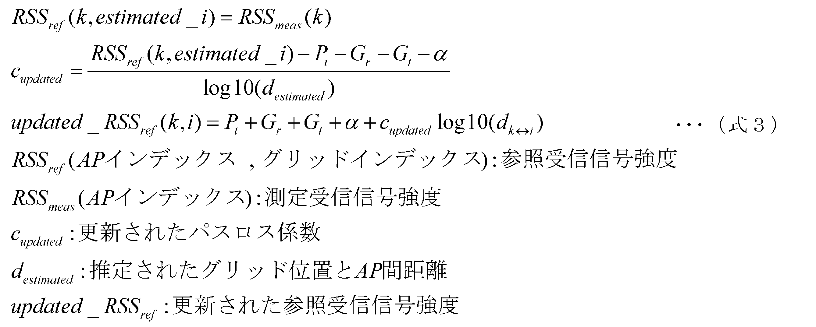
 図4は、本発明の実施形態1の測位サーバの構成を示すブロック図、図5は、測位対象のクライアントが存在しえる範囲の変動パターンとフィンガープリントとの対応関係を説明する図である。
(Embodiment 1)
FIG. 4 is a block diagram illustrating the configuration of the positioning server according to the first embodiment of the present invention, and FIG. 5 is a diagram illustrating a correspondence relationship between a variation pattern of a range in which a positioning target client may exist and a fingerprint.
 実施形態1の測位サーバは、電波マップ管理部10、固定フィンガープリント管理部11、拡張フィンガープリント管理部12、測位部13、パラメータ保持部14、フィンガープリント更新部15を備えている。 The positioning server according to the first embodiment includes a radio wave map management unit 10, a fixed fingerprint management unit 11, an extended fingerprint management unit 12, a positioning unit 13, a parameter holding unit 14, and a fingerprint update unit 15.
 電波マップ管理部10は、アクセスポイントAPとクライアントCLとの間で伝送される電波の測定情報(以下、代表的に受信信号強度を用いる)と空間位置との対応関係を推定的に表わす電波マップデータ(例えばフィンガープリント)を管理する。本実施形態においては、電波マップ管理部10は、固定フィンガープリント管理部11及び拡張フィンガープリント管理部12により構成される。 The radio wave map management unit 10 is a radio wave map that preferentially represents a correspondence relationship between measurement information (hereinafter, representatively using received signal strength) of radio waves transmitted between the access point AP and the client CL and a spatial position. Manage data (eg fingerprints). In the present embodiment, the radio wave map management unit 10 includes a fixed fingerprint management unit 11 and an extended fingerprint management unit 12.
 固定フィンガープリント管理部11は、測位対象のクライアントが通常時に存在しえる空間範囲として設定された固定測位範囲(図5参照)のフィンガープリント(以下、固定フィンガープリントとも呼ぶ)を保持(記憶及び管理)している。固定フィンガープリントは、測位サーバに接続されるアクセスポイントAP(あるいは基地局、アクセスノードとも呼ぶ)の各々について作成され、保持されている。この固定フィンガープリントは、測位処理に必要なときに固定フィンガープリント管理部11によって読み出されて測位部13に出力される。また、固定フィンガープリント管理部11には、フィンガープリント更新部15から逐次更新された更新データが入力され、固定フィンガープリントの全体あるいは一部のデータが置き換えられて更新される。 The fixed fingerprint management unit 11 holds (stores and manages) a fingerprint (hereinafter also referred to as a fixed fingerprint) of a fixed positioning range (see FIG. 5) set as a spatial range in which a positioning target client can exist at normal times. )is doing. A fixed fingerprint is created and held for each access point AP (or also called a base station or access node) connected to the positioning server. The fixed fingerprint is read by the fixed fingerprint management unit 11 and output to the positioning unit 13 when necessary for the positioning process. The fixed fingerprint management unit 11 is input with update data sequentially updated from the fingerprint update unit 15 and is updated by replacing all or part of the fixed fingerprint data.
 なお、固定フィンガープリント管理部11は、通信ネットワークあるいは通信リンク上の別の記憶装置あるいは別の測位サーバなどの処理装置に固定フィンガープリントを保持させ、これを通信ネットワークあるいは通信リンクを介して読み書き可能なように構成してもよい。このようにすることで、本実施形態の測位システムでは、測位サーバのハードウェア規模を削減できる。さらに、本実施形態の測位システムでは、複数の測位サーバで同じAPのフィンガープリントを共有する場合には、1測位サーバあたりのフィンガープリントを更新する処理負荷を低減することが可能となる。 The fixed fingerprint management unit 11 allows a processing device such as another storage device or another positioning server on the communication network or communication link to hold the fixed fingerprint, and can read and write it through the communication network or communication link. You may comprise as follows. By doing in this way, in the positioning system of this embodiment, the hardware scale of a positioning server can be reduced. Furthermore, in the positioning system of the present embodiment, when a plurality of positioning servers share the same AP fingerprint, the processing load for updating the fingerprint per positioning server can be reduced.
 拡張フィンガープリント管理部12は、測位対象のクライアントが特定の期間あるいは状態などの特定の条件下においてのみ存在しえる空間範囲として設定された拡張測位範囲(図5参照)のフィンガープリントを保持(記憶及び管理)している。以下、この拡張測位範囲のフィンガープリントを、拡張フィンガープリントとも呼ぶ。 The extended fingerprint management unit 12 holds (stores) a fingerprint of an extended positioning range (see FIG. 5) set as a spatial range in which a positioning target client can exist only under a specific condition such as a specific period or state. And management). Hereinafter, the fingerprint of the extended positioning range is also referred to as an extended fingerprint.
 この拡張測位範囲は、固定フィンガープリント管理部11が保持する固定フィンガープリントが適用される固定測位範囲に対して追加拡張されるものである。例えば、他の測位サーバが保持する固定測位範囲と重なるような範囲が拡張測位範囲とされる。すなわち、拡張測位範囲は、他の測位サーバの固定測位範囲に存在するクライアントに対して測位を担うように設定される範囲となる。従って、通常であれば、拡張測位範囲に存在するクライアントは、他の測位サーバの測位対象となり、本測位サーバの測位対象となる期間あるいは状態などの条件は限定されたものとなる。 This extended positioning range is additionally extended with respect to the fixed positioning range to which the fixed fingerprint held by the fixed fingerprint management unit 11 is applied. For example, a range that overlaps a fixed positioning range held by another positioning server is set as an extended positioning range. That is, the extended positioning range is a range that is set so as to perform positioning for clients existing in the fixed positioning range of another positioning server. Therefore, normally, a client that exists in the extended positioning range is a positioning target of another positioning server, and conditions such as a period or a state that is a positioning target of this positioning server are limited.
 拡張フィンガープリントは、測位サーバに接続されるAPの各々について作成され、保持されている。拡張フィンガープリントは、測位処理に必要なときに拡張フィンガープリント管理部12によって読み出されて測位部13に出力される。また、拡張フィンガープリント管理部12には、フィンガープリント更新部15で逐次更新された更新データが入力され、拡張フィンガープリントのデータの全体あるいは一部が置き換えられて更新される。 The extended fingerprint is created and held for each AP connected to the positioning server. The extended fingerprint is read by the extended fingerprint management unit 12 and output to the positioning unit 13 when necessary for the positioning process. Also, the extended fingerprint management unit 12 receives the update data sequentially updated by the fingerprint update unit 15, and is updated by replacing all or part of the extended fingerprint data.
 なお、拡張フィンガープリント管理部12は、通信ネットワークあるいは通信リンク上の別の記憶装置あるいは別の測位サーバなどの処理装置に拡張フィンガープリントを保持させてもよい。そして、拡張フィンガープリント管理部12は、上記の拡張フィンガープリントを通信ネットワークあるいは通信リンクを介して読み書き可能なように構成してもよい。このようにすることで、本実施形態の測位システムでは、測位サーバのハードウェア規模を削減でき、さらに、複数の測位サーバで同じAPのフィンガープリントを共有する場合には、1測位サーバあたりのフィンガープリントを更新する処理負荷を低減することが可能となる。 The extended fingerprint management unit 12 may hold the extended fingerprint in a processing device such as another storage device or another positioning server on the communication network or communication link. The extended fingerprint management unit 12 may be configured so that the above-described extended fingerprint can be read and written via a communication network or a communication link. By doing in this way, in the positioning system of this embodiment, the hardware scale of a positioning server can be reduced. Furthermore, when a plurality of positioning servers share the same AP fingerprint, the number of fingers per positioning server It is possible to reduce the processing load for updating the print.
 測位部13は、配下APを介して入力端子から入力されたクライアントからの受信信号強度情報、固定フィンガープリント管理部11から取得した固定フィンガープリント、および、拡張フィンガープリント管理部12から取得した拡張フィンガープリントを用いて、クライアントの測位を実行する。ここで、配下APとは、測位サーバに接続されてクライアントの測位のためにクライアントへ信号(例えばビーコン)を送信するとともに、自局のフィンガープリントが測位サーバに保持されている一つ以上のAPのことである。また、測位部13は、測位結果を出力端子に出力して、例えばAPを介してクライアントへ位置情報を提供する。 The positioning unit 13 receives the received signal strength information from the client input from the input terminal via the subordinate AP, the fixed fingerprint acquired from the fixed fingerprint management unit 11, and the extended fingerprint acquired from the extended fingerprint management unit 12. Perform client positioning using print. Here, the subordinate AP is one or more APs that are connected to the positioning server and transmit a signal (for example, a beacon) to the client for positioning by the client, and the fingerprint of the local station is held in the positioning server. That is. Further, the positioning unit 13 outputs the positioning result to the output terminal, and provides the position information to the client via, for example, the AP.
 パラメータ保持部14は、配下APの使用周波数、配下APの設置位置、配下APの送信電力値、配下APのアンテナゲイン、配下APに対するフィンガープリントを求めるために使用されるパスロス係数、クライアントのアンテナゲインなどのパラメータを保持し、管理する。 The parameter holding unit 14 uses the frequency of the subordinate AP, the installation position of the subordinate AP, the transmission power value of the subordinate AP, the antenna gain of the subordinate AP, the path loss coefficient used for obtaining the fingerprint for the subordinate AP, and the antenna gain of the client Maintain and manage parameters such as.
 フィンガープリント更新部15は、次の1、2、3の情報を用いて、APのパスロス係数及びクライアントのアンテナゲインなどのパラメータを推定あるいは導出する。1、測位部13で使われたクライアントからの受信信号強度情報、2、測位部13で得られたクライアントの測位結果、3、パラメータ保持部14で保持されているパラメータの値。そして、フィンガープリント更新部15は、パラメータ保持部14が管理する情報を更新する。また、フィンガープリント更新部15は、この更新したパラメータを用いて、APのフィンガープリントを更新する。さらにフィンガープリント更新部15は、更新したフィンガープリントの固定測位範囲に対応する部分を固定フィンガープリント管理部11へ、拡張測位範囲に対応する部分を拡張フィンガープリント管理部12へ出力する。固定フィンガープリント管理部11及び拡張フィンガープリント管理部12は、各々保持するフィンガープリントのデータを更新する。 The fingerprint update unit 15 estimates or derives parameters such as an AP path loss coefficient and a client antenna gain by using the following information 1, 2, and 3. 1, received signal strength information from the client used in the positioning unit 13, 2, the positioning result of the client obtained in the positioning unit 13, 3, the parameter value held in the parameter holding unit 14. Then, the fingerprint update unit 15 updates the information managed by the parameter holding unit 14. Further, the fingerprint update unit 15 updates the fingerprint of the AP using the updated parameter. Furthermore, the fingerprint update unit 15 outputs a portion corresponding to the fixed positioning range of the updated fingerprint to the fixed fingerprint management unit 11 and a portion corresponding to the extended positioning range to the extended fingerprint management unit 12. Each of the fixed fingerprint management unit 11 and the extended fingerprint management unit 12 updates the fingerprint data held therein.
 フィンガープリント更新部15は、主に、固定測位範囲におけるクライアントの測位結果を用いて、固定測位範囲におけるパスロス係数等のパラメータを推定あるいは導出し、更新する。通常、人の混雑状況などが異なるため、固定測位範囲と拡張測位範囲とでは、フィンガープリントを決定するパラメータの相関は低くなる。しかしながら、クライアントが固定測位範囲から拡張測位範囲へ移動可能となる特定期間(例えば電車車両のドアが開いた期間)には、人の混雑状況などが関係しあって、固定測位範囲と拡張測位範囲とは、フィンガープリントを決定するパラメータの相関が高くなる。フィンガープリント更新部15は、上記の現象を考慮して、固定測位範囲において推定あるいは導出し、更新したパスロス係数などのパラメータを用いて、固定フィンガープリントの更新を行うとともに、拡張フィンガープリントの更新も同様に行うことができる。 Fingerprint update unit 15 mainly estimates or derives parameters such as a path loss coefficient in the fixed positioning range and updates using the positioning result of the client in the fixed positioning range. Usually, since the congestion situation of people is different, the correlation between parameters for determining the fingerprint is low in the fixed positioning range and the extended positioning range. However, the fixed positioning range and the extended positioning range are related to the congestion of people during a specific period (for example, the period when the train car door is opened) during which the client can move from the fixed positioning range to the extended positioning range. And the correlation of parameters for determining the fingerprint becomes high. In consideration of the above phenomenon, the fingerprint update unit 15 estimates or derives in the fixed positioning range, updates the fixed fingerprint by using the updated parameter such as the path loss coefficient, and also updates the extended fingerprint. The same can be done.
 なお、フィンガープリント更新部15は、固定フィンガープリントの更新頻度よりも少ない頻度で拡張フィンガープリントの更新を行ってもよい。拡張測位範囲は測位対象のクライアントが存在しえる時間あるいは状態などの条件が限られる。そのため、特にクライアントが拡張測位範囲に存在する条件に合致しない場合などには、フィンガープリント更新部15は、拡張フィンガープリントの更新頻度を少なくすることができる。少なくしても、測位精度への影響は抑えられる。従って、測位精度に与える影響は抑えながら、フィンガープリント更新部15は処理負荷を低減できる。 Note that the fingerprint update unit 15 may update the extended fingerprint at a frequency less than the fixed fingerprint update frequency. The extended positioning range is limited in conditions such as time or state in which a client to be positioned can exist. Therefore, particularly when the client does not meet the conditions existing in the extended positioning range, the fingerprint update unit 15 can reduce the update frequency of the extended fingerprint. Even if it is reduced, the influence on positioning accuracy can be suppressed. Therefore, the fingerprint update unit 15 can reduce the processing load while suppressing the influence on the positioning accuracy.
 以上の構成を有する本実施形態に対応する測位サーバの動作を、AP及びクライアントの動作も含めて説明する。 The operation of the positioning server corresponding to the present embodiment having the above configuration will be described including the operations of the AP and the client.
 測位サーバに接続されたAPは、配下のクライアントに対してビーコン信号あるいはポーリングパケットを送信する。APは、ビーコン信号あるいはポーリングパケットを、所定の周期で送信してもよいし、特定のタイミングで送信してもよい。またAPは所定の送信電力で送信してもよい。さらには、APは、ビーコン信号あるいはポーリングパケットに自局ID(例えば、SSID、MACアドレス、測位に特化した識別情報などのうち一つあるいは複数の組み合わせ)を含めて送信してもよい。これによりクライアントがAPを正しく識別することができる。 The AP connected to the positioning server transmits a beacon signal or a polling packet to the subordinate clients. The AP may transmit a beacon signal or a polling packet at a predetermined period, or may transmit at a specific timing. The AP may transmit with a predetermined transmission power. Furthermore, the AP may transmit a beacon signal or a polling packet including its own station ID (for example, one or a combination of SSID, MAC address, identification information specialized for positioning, etc.). This allows the client to correctly identify the AP.
 なお、ビーコン信号あるいはポーリングパケットは、測位サーバが送信するものであってもよい。測位サーバが送信したビーコン信号あるいはポーリングパケットは、配下AP経由でクライアントに配信される。これにより、特定のクライアントを指定して測位を実施するような場合に、測位サーバは、対象となるクライアントを指定することができる。すなわち、汎用APを用いてシステム構築できることから、測位システムの柔軟性あるいは自由度が向上する(APがビーコン信号を送信する場合では、測位サーバがAPに対して対象クライアントを指定する必要があり、APと測位サーバとの間のプロトコルが必要となる。つまり、特定のAPを用いてシステム構築することが制約となる場合には自由度が低下することになる)。また、ビーコン信号あるいはポーリングパケットは、特定のクライアントに対してユニキャスト送信されるものであってもよいし、特定のクライアント群にマルチキャスト、あるいは配下の全クライアントにブロードキャストで通知されるものであってもよい。 Note that the beacon signal or polling packet may be transmitted by the positioning server. The beacon signal or polling packet transmitted by the positioning server is delivered to the client via the subordinate AP. Thereby, when performing positioning by designating a specific client, the positioning server can designate a target client. That is, since the system can be constructed using a general-purpose AP, the flexibility or flexibility of the positioning system is improved (when the AP transmits a beacon signal, the positioning server needs to specify the target client for the AP, A protocol between the AP and the positioning server is required, that is, the degree of freedom is reduced when the system construction using a specific AP is a constraint). Further, the beacon signal or polling packet may be unicast transmitted to a specific client, or multicast to a specific client group or broadcast to all subordinate clients. Also good.
 以下、特にビーコン信号が配下APから送信される場合について説明する。 Hereinafter, a case where a beacon signal is transmitted from a subordinate AP will be described.
 クライアントは、自局が受信したAPからのビーコンの受信信号強度を測定し、受信したAPのID(識別情報:MACアドレスなど)と測定した受信信号強度とをセット(対)にした受信信号強度情報を、接続しているAPまたは測位サーバへ送信する。このときクライアントは、受信信号強度情報とともに自局ID(例えばIPアドレス、MACアドレス、あるいは測位に特化した識別情報など)を付加して送信してもよい。自局IDの付加により、測位サーバはクライアントを特定の端末として識別することができる。 The client measures the received signal strength of the beacon from the AP received by the local station, and the received signal strength is a set (pair) of the received AP ID (identification information: MAC address, etc.) and the measured received signal strength. Information is transmitted to the connected AP or positioning server. At this time, the client may add its own station ID (for example, an IP address, a MAC address, or identification information specialized for positioning) together with the received signal strength information for transmission. By adding the local station ID, the positioning server can identify the client as a specific terminal.
 クライアントが受信信号強度情報をAPに送信した後、APは受信信号強度情報を測位サーバに転送する。このとき、APは、受信信号強度情報にクライアントのIDを付加して送信してもよい。これにより、クライアントが受信信号強度情報に自局IDを付加しないような場合においても、測位サーバはクライアントを正しく識別することができる。 After the client sends the received signal strength information to the AP, the AP transfers the received signal strength information to the positioning server. At this time, the AP may transmit the received signal strength information with the client ID added. Thereby, even when the client does not add its own station ID to the received signal strength information, the positioning server can correctly identify the client.
 測位サーバは、固定フィンガープリント管理部11に、配下APの固定フィンガープリントを保持し、拡張フィンガープリント管理部12に、配下APの拡張フィンガープリントを保持する。また、測位サーバは、パラメータ保持部14に、パスロス係数、配下APのアンテナゲイン、クライアントの想定アンテナゲインなどのパラメータを保持する。そして、測位サーバは、入力端子から、配下APを介してクライアントから報告されるAPのID(MACアドレスなど)および受信信号強度(以降、これらをあわせて受信信号強度情報と呼ぶ)を入力する。この入力を受けて、測位部13は、該当(測位対象)のクライアントが報告したAPに関する固定フィンガープリントおよび拡張フィンガープリントを、固定フィンガープリント管理部11および拡張フィンガープリント管理部12から取得する。そして、測位部13は、該当のクライアントが報告したAPに関する受信信号強度情報を用いて、例えば、上述した式2を使って、測位位置として求める。具体的には、測位部13は、フィンガープリントの参照受信信号強度と測定された受信信号強度との自乗誤差が最小になるグリッド位置を、上記測位位置として求める。測位部13は、求めた測位位置と測位に使用したAPに関する受信信号強度情報とをフィンガープリント更新部15に出力する。また、測位部13は、測位位置と測位したクライアントのクライアントIDとを出力端子に出力する。 The positioning server holds the fixed fingerprint of the subordinate AP in the fixed fingerprint management unit 11, and holds the extended fingerprint of the subordinate AP in the extended fingerprint management unit 12. In addition, the positioning server holds parameters such as a path loss coefficient, an antenna gain of a subordinate AP, and an assumed antenna gain of a client in the parameter holding unit 14. Then, the positioning server inputs the ID (MAC address or the like) of the AP and the received signal strength (hereinafter collectively referred to as received signal strength information) reported from the client via the subordinate AP from the input terminal. In response to this input, the positioning unit 13 acquires the fixed fingerprint and the extended fingerprint related to the AP reported by the corresponding (positioning target) client from the fixed fingerprint management unit 11 and the extended fingerprint management unit 12. And the positioning part 13 calculates | requires as a positioning position, for example using Formula 2 mentioned above using the received signal strength information regarding AP which the applicable client reported. Specifically, the positioning unit 13 obtains the grid position where the square error between the reference received signal strength of the fingerprint and the measured received signal strength is minimized as the positioning position. The positioning unit 13 outputs the obtained positioning position and received signal strength information regarding the AP used for positioning to the fingerprint updating unit 15. In addition, the positioning unit 13 outputs the positioning position and the client ID of the positioned client to the output terminal.
 フィンガープリント更新部15は、測位部13から、測位位置と、クライアントにより実測及び報告されて測位に用いたAPに関する受信信号強度情報とを入力すると、パラメータ保持部14から前記保持するパラメータを読み出す。そして、これらを用いて、フィンガープリント更新部15は、例えば、上述した式3を用いて、APに関するパラメータを推定し更新する。さらに、フィンガープリント更新部15は、これらの更新したパラメータを用いて、APのフィンガープリントを更新する。 When the fingerprint updating unit 15 inputs the positioning position and the received signal strength information regarding the AP measured and reported by the client and used for positioning from the positioning unit 13, the fingerprint updating unit 15 reads the stored parameter from the parameter holding unit 14. And using these, the fingerprint update part 15 estimates and updates the parameter regarding AP, for example using Formula 3 mentioned above. Further, the fingerprint update unit 15 updates the fingerprint of the AP using these updated parameters.
 固定測位範囲と拡張測位範囲との実伝搬環境は相関すると考えられる。従って、フィンガープリント更新部15は、固定測位範囲の受信信号強度情報に基づきパラメータの値が更新された場合でも、このパラメータの値を用いて拡張フィンガープリントの更新も行う。 The actual propagation environment between the fixed positioning range and the extended positioning range is considered to be correlated. Therefore, even when the parameter value is updated based on the received signal strength information of the fixed positioning range, the fingerprint update unit 15 also updates the extended fingerprint using the parameter value.
 そして、フィンガープリント更新部15は、更新したフィンガープリントのうち固定測位範囲に対応する部分を固定フィンガープリント管理部11へ、拡張測位範囲に対応する部分を拡張フィンガープリント管理部12へ出力する。また、更新したパラメータはパラメータ保持部14に出力する。 Then, the fingerprint update unit 15 outputs a part corresponding to the fixed positioning range to the fixed fingerprint management unit 11 and a part corresponding to the extended positioning range to the extended fingerprint management unit 12 in the updated fingerprint. The updated parameters are output to the parameter holding unit 14.
 APは、測位サーバからクライアントIDと測位結果を含むメッセージとを受信すると、該当のクライアントへ測位結果を送信(転送)する。このとき、測位サーバは、測位に用いたフィンガープリントの種別をさらにメッセージに含め、クライアントに通知してもよい。例えば、測位サーバは、フィンガープリントを特定する識別子を通知してもよい。この識別子は、固定測位範囲あるいは拡張測位範囲を対象に測位を行ったか、すなわち固定フィンガープリントあるいは拡張フィンガープリントのいずれを用いたか(さらに詳細に、どの拡張フィンガープリントを用いたか)、という情報を示す。これにより、特に拡張フィンガープリントを用いて測位が行われた場合に、クライアントは、適したタイミングで適切なサーバへの切り替え(ハンドオーバ)を判断し、開始することができる。 When the AP receives the client ID and the message including the positioning result from the positioning server, the AP transmits (transfers) the positioning result to the corresponding client. At this time, the positioning server may further include the fingerprint type used for positioning in the message and notify the client. For example, the positioning server may notify an identifier that identifies the fingerprint. This identifier indicates information indicating whether the positioning is performed in the fixed positioning range or the extended positioning range, that is, whether the fixed fingerprint or the extended fingerprint is used (more specifically, which extended fingerprint is used). . Thereby, especially when positioning is performed using the extended fingerprint, the client can determine and start switching (handover) to an appropriate server at an appropriate timing.
 なお、固定フィンガープリント管理部11は、保持する固定測位範囲の初期データとして、予めAPが保持する固定測位範囲のグリッド位置において別の測定装置が実測した受信信号強度のデータを保持してもよい。このように、初期データを実測に基づき保有することにより、測位サーバは、フィンガープリントが実環境に適合するまで待つことなく測位を開始できる。 The fixed fingerprint management unit 11 may hold, as initial data of the fixed positioning range to be held, received signal strength data actually measured by another measuring apparatus at the grid position of the fixed positioning range held by the AP in advance. . Thus, by storing the initial data based on the actual measurement, the positioning server can start positioning without waiting until the fingerprint is adapted to the actual environment.
 あるいは、固定フィンガープリント管理部11は、上記固定測位範囲の初期データとして、固定測位範囲のグリッド位置における受信信号強度を計算した初期データを保持してもよい。受信信号強度の計算は、予めパスロス係数を実測等により推測し、Friis equation(式1)として知られている距離減衰式などを用いて行うことができる。 Alternatively, the fixed fingerprint management unit 11 may hold initial data obtained by calculating the received signal strength at the grid position of the fixed positioning range as the initial data of the fixed positioning range. The calculation of the received signal strength can be performed by estimating a path loss coefficient in advance by actual measurement or the like and using a distance attenuation formula known as Friis equation (Equation 1).
 さらに、拡張フィンガープリント管理部12は、保持する拡張測位範囲の初期データとして、予めAPが保持する拡張測位範囲のグリッド位置において実測した受信信号強度のデータを保持してもよい。このように、初期データを実測に基づき保有することにより、測位サーバは、フィンガープリントが実環境に適合するまで待つことなく測位を開始できる。 Furthermore, the extended fingerprint management unit 12 may hold data of received signal strength actually measured at the grid position of the extended positioning range held by the AP in advance as initial data of the extended positioning range to be held. Thus, by storing the initial data based on the actual measurement, the positioning server can start positioning without waiting until the fingerprint is adapted to the actual environment.
 あるいは、拡張フィンガープリント管理部12は、上記拡張測位範囲の初期データとして、APの拡張測位範囲のグリッド位置に対応する受信信号強度を計算したデータを保持してもよい。受信信号強度の計算は、予め得られたAPの固定測位範囲での受信信号強度情報及びパスロス係数、固定測位範囲での構造情報(壁などの反射物がどこにあるか等)、APの設置位置などからFriis equation(式1)などの距離減衰式を用いて行うことができる。 Alternatively, the extended fingerprint management unit 12 may hold data obtained by calculating the received signal strength corresponding to the grid position of the extended positioning range of the AP as the initial data of the extended positioning range. The received signal strength is calculated based on the received signal strength information and path loss coefficient obtained in advance in the fixed positioning range of the AP, the structure information in the fixed positioning range (where the reflecting object such as the wall is, etc.), the installation position of the AP From the above, it can be performed using a distance attenuation formula such as Friis equation (Formula 1).
 ここで、測位サーバが電車車両に搭載され、電車車内の領域が固定測位範囲に、且つ電車車外の領域が拡張測位範囲に設定されている場合を想定する。この場合、始発時などには、固定測位範囲と拡張測位範囲との実伝搬環境は相関しない。また、始発時であっても、プラットホームと電車車内との状況は、駅によって、同一になる場合と、全く異なる場合とに分かれる。プラットホームと電車車内との状況は、プラットホームのクライアントがまばらであれば同一となる一方、プラットホームが混雑していれば全く異なる。従って、このような状況を考慮して、本実施の形態の測位システムは、駅ごとまたは始発の時間帯ごとの混雑統計情報をデータベース化して保持してもよい。そして、固定フィンガープリント管理部11は、上記の混雑統計情報に基づき定められた電車車内のフィンガープリントの初期データを保持してもよい。 Here, it is assumed that the positioning server is mounted on a train car, the area inside the train car is set as a fixed positioning range, and the area outside the train car is set as an extended positioning range. In this case, the actual propagation environment between the fixed positioning range and the extended positioning range is not correlated at the first departure. Even at the first departure, the situation between the platform and the train car is divided into a case where it is the same and a case where it is completely different depending on the station. The situation between the platform and the train is the same if the platform clients are sparse, but completely different if the platform is congested. Therefore, in consideration of such a situation, the positioning system according to the present embodiment may store the congestion statistical information for each station or each initial time zone in a database. And the fixed fingerprint management part 11 may hold | maintain the initial data of the fingerprint in a train car defined based on said congestion statistical information.
 図6は、拡張フィンガープリントによる作用を説明する図である。 FIG. 6 is a diagram for explaining the action of the extended fingerprint.
 この実施形態1の測位サーバによれば、固定フィンガープリント管理部11は、固定測位範囲のフィンガープリントを保持している。それに加えて、拡張フィンガープリント管理部12は、測位対象のクライアントが固定測位範囲以外で移動しえる全ての測位範囲(拡張測位範囲)をカバーした拡張フィンガープリントを保持している。さらに、フィンガープリント更新部15は、これらのフィンガープリントを所定の時点における伝搬環境に対応できるように、逐次更新している。したがって、この実施形態1の測位サーバでは、測位範囲外に測位対象のクライアントが移動してしまうことによる測位精度の劣化が低減される。 According to the positioning server of the first embodiment, the fixed fingerprint management unit 11 holds the fingerprint of the fixed positioning range. In addition, the extended fingerprint management unit 12 holds an extended fingerprint that covers all positioning ranges (extended positioning ranges) in which the client to be positioned can move outside the fixed positioning range. Furthermore, the fingerprint update unit 15 sequentially updates these fingerprints so that they can correspond to the propagation environment at a predetermined time. Therefore, in the positioning server of the first embodiment, the degradation of positioning accuracy due to the movement of the positioning target client outside the positioning range is reduced.
 例えば、図6Bに示すように、実施形態1の測位サーバSV1が、電車車両に搭載され、電車車両内にのみ固定測位範囲が設定されている場合を想定する。この場合、電車のドアが開いてクライアントCL1がプラットホームへ移動(○の位置)した際、電車車両内に設置された配下AP(AP1、AP2)は、プラットホーム上のクライアントCL1へ信号を送信してしまうことがある。この信号の送信は、クライアントCLが電車車両内のAP(AP1、AP2)からプラットホームのAPへハンドオーバを完了するまでの期間に行われる。そして、この信号の受信信号強度RSS1、RSS2の情報がクライアントCL1から報告されると、測位サーバSV1は、測位処理を実行する。この場合、拡張フィンガープリントにより測位対象の空間範囲がプラットホームまで対応しているので、測位サーバSV1は、このクライアントCL1の位置d(★の位置)を高精度に測定することができる(○の位置と★の位置とが一致する)。従って、その後に、フィンガープリント更新部15がフィンガープリントを誤って更新するということが回避される。 For example, as shown in FIG. 6B, it is assumed that the positioning server SV1 of the first embodiment is mounted on a train car and a fixed positioning range is set only in the train car. In this case, when the train door opens and the client CL1 moves to the platform (position of ○), the subordinate APs (AP1, AP2) installed in the train car send a signal to the client CL1 on the platform. It may end up. This signal is transmitted during a period until the client CL completes the handover from the AP (AP1, AP2) in the train car to the platform AP. Then, when the information of the received signal strengths RSS1 and RSS2 of this signal is reported from the client CL1, the positioning server SV1 executes a positioning process. In this case, since the spatial range of the positioning target corresponds to the platform by the extended fingerprint, the positioning server SV1 can measure the position d (the position of ★) of the client CL1 with high accuracy (the position of the circle). And the position of ★ match). Accordingly, it is avoided that the fingerprint update unit 15 subsequently updates the fingerprint by mistake.
 また、図6Aのように、電車がプラットホームに停止している状態で電車のドアが閉じている期間を想定する。この期間では、測位サーバSV1は、固定フィンガープリントだけでなく、クライアントCL1が存在しえないドア外の範囲(拡張測位範囲)を対象とする拡張フィンガープリントも使用してクライアントの測位を行うことになる。このため、測位部13が、クライアントCL1の測位結果をドアの外である拡張測位範囲の位置として求めてしまう、ということが否定できない。しかしながらこの場合は、図6Aに示すように、実際にはクライアントCL1は車両内に位置しているため、測位サーバSV1は、拡張フィンガープリントが使用可能であっても、実際には固定フィンガープリントを用いて測位を行う。そのため、測位サーバSV1は、クライアントCL1の実際の位置(○の位置)と測位位置c(★の位置)との誤差を抑えることができる(○の位置と★の位置とのずれは、もともと固定フィンガープリントのみで測位を行った場合の誤差と同じ程度の誤差に抑えられる)。従って、測位精度の劣化は生じない。また、測位結果に大きな誤差が含まれないので、その後に、フィンガープリント更新部15がフィンガープリントを大きな誤差を含んで更新してしまうということもない。 Suppose that the train door is closed while the train is stopped on the platform, as shown in FIG. 6A. In this period, the positioning server SV1 performs client positioning using not only a fixed fingerprint but also an extended fingerprint for a range outside the door (extended positioning range) where the client CL1 cannot exist. Become. For this reason, it cannot be denied that the positioning unit 13 determines the positioning result of the client CL1 as the position of the extended positioning range outside the door. However, in this case, as shown in FIG. 6A, since the client CL1 is actually located in the vehicle, the positioning server SV1 does not actually use the fixed fingerprint even if the extended fingerprint can be used. Use for positioning. Therefore, the positioning server SV1 can suppress an error between the actual position (◯ position) of the client CL1 and the positioning position c (★ position) (the deviation between the ○ position and the ★ position is originally fixed). It can be suppressed to the same level of error as when positioning is performed using only the fingerprint). Therefore, the positioning accuracy does not deteriorate. Further, since a large error is not included in the positioning result, the fingerprint update unit 15 does not update the fingerprint with a large error thereafter.
(実施形態2)
 図7は、本発明の実施形態2の測位サーバの構成を示すブロック図である。実施形態2の測位サーバには、実施形態1の構成に加えて、測位範囲判断部21が追加されている。実施形態1と同様の構成は、同一符号を付して説明を省略する。
(Embodiment 2)
FIG. 7 is a block diagram illustrating a configuration of the positioning server according to the second embodiment of the present invention. In addition to the configuration of the first embodiment, a positioning range determination unit 21 is added to the positioning server of the second embodiment. The same configurations as those of the first embodiment are denoted by the same reference numerals and description thereof is omitted.
 測位範囲判断部21は、拡張測位範囲のうち、その時点において測位範囲に含める部分と含めない部分とを判断する。すなわち、拡張測位範囲の中にも、所与の時点または条件に応じて、測位対象クライアントが存在する可能性が生じる部分と、可能性がない、あるいはほとんどない部分とが生じえる。そのため、前者のみを測位範囲に含め、後者を測位範囲から除外する目的である。固定測位範囲は、測位対象のクライアントが通常時に存在しえる範囲であるので、常に測位範囲に含められる。 The positioning range determination unit 21 determines a portion included in the positioning range and a portion not included in the positioning range at that time in the extended positioning range. That is, in the extended positioning range, depending on a given time point or condition, there may be a portion where there is a possibility that the positioning target client exists and a portion where there is no possibility or almost no possibility. Therefore, the purpose is to include only the former in the positioning range and exclude the latter from the positioning range. The fixed positioning range is always included in the positioning range because the client to be positioned can exist at normal time.
 なお、特定の条件下においては、測位範囲判断部21は、固定測位領域であっても、この領域を測位対象から外すようにしてもよい。例えば、終着駅等で全ての乗客が降車したことを認識できた場合は、測位範囲判断部21は、固定測位領域をはずして拡張測位領域のみ対象にして、測位部13が測位を実施してもよい。これにより、測位部13は、クライアントが存在しない領域に対する測位処理を抑えることができ、全体の処理量または処理負荷を低減できる。 Note that, under specific conditions, the positioning range determination unit 21 may exclude a fixed positioning area from the positioning target. For example, when it is possible to recognize that all passengers get off at the terminal station or the like, the positioning range determination unit 21 removes the fixed positioning region and targets only the extended positioning region, and the positioning unit 13 performs positioning. Also good. Thereby, the positioning part 13 can suppress the positioning process with respect to the area | region where a client does not exist, and can reduce the whole processing amount or processing load.
 また、測位対象のクライアントが拡張測位範囲に存在しえない期間(例えば車両のドアが閉まっている期間、車両が走行している期間、など)または状態(例えば車両のドアが閉まっている状態、車両が走行している状態、など)などの特定条件下であっても、測位範囲判断部21は、拡張測位範囲を測位範囲に含めてもよい。この場合でも、実施形態1で説明したように、大きな不都合は生じない。従って、測位範囲判断部21は、拡張測位範囲のうち測位範囲に含める部分と含めない部分とを変動させる場合に、測位範囲から一部を除外する際の条件あるいは期間の判断を厳格に行い、測位範囲に一部を含める際の条件あるいは期間の判断を寛容に行うようにしてよい。このようにすることで、測位サーバは、測位対象のクライアントが測位範囲外に存在することになって大きな測位誤差を発生させてしまうことを回避することができる。 In addition, a period during which the client to be positioned cannot exist in the extended positioning range (for example, a period in which the vehicle door is closed, a period in which the vehicle is traveling, etc.) or a state (for example, a state in which the vehicle door is closed, The positioning range determination unit 21 may include the extended positioning range in the positioning range even under specific conditions such as a state where the vehicle is traveling. Even in this case, as described in the first embodiment, no major inconvenience occurs. Therefore, the positioning range determination unit 21 strictly determines a condition or a period when excluding a part from the positioning range when changing the portion included in the positioning range and the portion not included in the extended positioning range, The condition or period for including a part in the positioning range may be tolerated. By doing in this way, the positioning server can avoid that the positioning target client exists outside the positioning range and causes a large positioning error.
 測位範囲判断部21は、配下APを介してクライアントから送られてくる受信信号強度情報に基づいて、拡張測位範囲のうち測位範囲に含める部分と除外する部分との判断を行う。この判断手法の具体例は後述の実施形態3から実施形態4に詳しく示す。或いは、測位範囲判断部21は、外部から補助情報を入力し、この補助情報に基づいて上記の判断を行ってもよい。補助情報には、例えば、クライアントが固定測位範囲から拡張測位範囲へ移動できるドアの開閉情報、開閉時間を表わす情報、または、ドアが複数ある場合に何れのドアが開くかを示す情報などを適用できる。 The positioning range determination unit 21 determines, based on the received signal strength information transmitted from the client via the subordinate AP, the portion to be included in the positioning range and the portion to be excluded from the extended positioning range. Specific examples of this determination method will be described in detail in Embodiments 3 to 4 described later. Alternatively, the positioning range determination unit 21 may input auxiliary information from the outside and make the above determination based on the auxiliary information. As auxiliary information, for example, door opening / closing information that allows the client to move from the fixed positioning range to the extended positioning range, information indicating the opening / closing time, or information indicating which door opens when there are multiple doors, etc. it can.
 また、測位サーバが電車車両に搭載される場合は、上記補助情報には、駅から電車車両の管理サーバに送信される入線指示情報、入線指示に対応した車内案内表示の切り替え信号、駅直前の信号機の切り替え信号(赤信号から青信号への切り替え信号)、電車車両の運行予定情報などを適用することができる。測位範囲判断部21は、このような情報に基づいて開閉されるドアの位置を導出するなどして、固定測位範囲(電車車内)から拡張測位範囲(プラットホーム)へクライアントが降車する可能性のない期間あるいは範囲を計算する。そして、測位範囲判断部21は、この範囲をその時点の測位範囲から除外する。例えば、電車車両の運行予定情報が入力された場合には、測位範囲判断部21は、現在時刻を参照しながらA駅からB駅へ移動している期間の測位範囲を固定測位範囲のみとする。と同時に、測位範囲判断部21は、B駅停車の1分間の測位範囲をドアの開く側の拡張測位範囲を含めたものに変動させることができる。 When the positioning server is mounted on a train car, the auxiliary information includes incoming line instruction information transmitted from the station to the train car management server, an in-vehicle guidance display switching signal corresponding to the incoming line instruction, A traffic signal switching signal (a switching signal from a red signal to a green signal), train schedule information, and the like can be applied. The positioning range determination unit 21 does not have a possibility that the client gets off from the fixed positioning range (in the train car) to the extended positioning range (platform) by deriving the position of the door that is opened and closed based on such information. Calculate duration or range. Then, the positioning range determination unit 21 excludes this range from the positioning range at that time. For example, when train schedule operation information is input, the positioning range determination unit 21 sets the positioning range during the period from the A station to the B station while referring to the current time as the fixed positioning range only. . At the same time, the positioning range determination unit 21 can change the one-minute positioning range at the B station stop to include the extended positioning range on the door opening side.
 ここで、電車車両の測位を第1測位サーバが担当し、プラットホームの測位を第2測位サーバが担当するシステムの場合を想定する。この場合、電車車両の始発駅においては、降車客が居ないため、測位範囲判断部21は、ドアが開く期間でも、第1測位サーバの測位範囲を固定測位範囲(電車車内)のみと判断してもよい。また、その際、測位範囲判断部21は、プラットホームの第2測位サーバの測位範囲を固定測位範囲(プラットホーム)と拡張測位範囲(電車車内)とに拡張するようにしてもよい。逆に、電車車両の終点駅においては、測位範囲判断部21は、これらの逆の態様で、第1測位サーバと第2測位サーバとの測位範囲を判断することができる。 Here, a case is assumed in which the first positioning server is in charge of the positioning of the train car and the platform is in charge of the positioning of the platform. In this case, since there is no passenger getting off at the first train station, the positioning range determination unit 21 determines that the positioning range of the first positioning server is only the fixed positioning range (within the train car) even during the door opening period. May be. At that time, the positioning range determination unit 21 may extend the positioning range of the second positioning server of the platform to a fixed positioning range (platform) and an extended positioning range (inside the train car). Conversely, at the terminal station of the train car, the positioning range determination unit 21 can determine the positioning ranges of the first positioning server and the second positioning server in the reverse manner.
 また、測位サーバがコンサートホール等のイベント設備内に設置され、ホールの出入り口に接する待合室は他の測位サーバが測位を行うような場合を想定する。この場合には、上記補助情報には、コンサート等の上演時間の情報を適用することができる。測位範囲判断部21は、このような情報に基づいて、コンサートの上演時間中はホール内のみを測位範囲と判断することができる。また、測位範囲判断部21は、上演終了後または休憩期間の測位範囲を、待合室あるいはロビーなどのホール外の範囲(拡張測位範囲)を含めたものに変動させることができる。 In addition, it is assumed that a positioning server is installed in an event facility such as a concert hall, and that the waiting room in contact with the entrance of the hall performs positioning by another positioning server. In this case, performance time information such as a concert can be applied to the auxiliary information. Based on such information, the positioning range determination unit 21 can determine only the inside of the hall as the positioning range during the concert performance time. In addition, the positioning range determination unit 21 can change the positioning range after the performance ends or during the break period to include a range outside the hall (extended positioning range) such as a waiting room or a lobby.
 測位範囲判断部21は、各条件に基づいて拡張測位範囲のうち測位範囲に含める部分と除外する部分とを判断したら、この情報を拡張フィンガープリント管理部12へ出力する。拡張フィンガープリント管理部12は、この情報により、除外された部分を省いて拡張フィンガープリントの残りの部分を測位部13に出力する。 The positioning range determination unit 21 outputs this information to the extended fingerprint management unit 12 after determining the portion to be included in the positioning range and the portion to be excluded from the extended positioning range based on each condition. Based on this information, the extended fingerprint management unit 12 omits the excluded part and outputs the remaining part of the extended fingerprint to the positioning unit 13.
 測位部13は、この一部分の拡張フィンガープリントと固定フィンガープリントとを用いてクライアントの測位処理を実行する。 The positioning unit 13 executes the positioning process of the client using this part of the extended fingerprint and the fixed fingerprint.
 なお、測位範囲判断部21は、拡張測位範囲のうち測位範囲に含める部分と除外する部分とを判断したら、この情報を、直接、測位部13へ出力するようにしてもよい。この場合、測位部13は、拡張フィンガープリント管理部12から入力される拡張フィンガープリントのうち測位範囲に含まれる部分のみを用いて測位用の演算を行うように構成すればよい。 The positioning range determination unit 21 may output this information directly to the positioning unit 13 after determining the portion to be included in the positioning range and the portion to be excluded from the extended positioning range. In this case, the positioning unit 13 may be configured to perform positioning calculation using only the portion included in the positioning range in the extended fingerprint input from the extended fingerprint management unit 12.
 また、実施形態2のフィンガープリント更新部15は、次のように、拡張フィンガープリントの更新を行うようにしてもよい。すなわち、全ての拡張測位範囲のうち、その時点で測位範囲に含まれる部分の拡張フィンガープリントの更新頻度を上げ、その時点で測位範囲から除外されている部分の拡張フィンガープリントの更新頻度を下げる。また、その際、フィンガープリント更新部15は、測位範囲に含まれる部分の拡張フィンガープリントの更新頻度と、固定フィンガープリントの更新頻度とを同一にしてもよい。このように更新頻度を調整することで、測位精度にあまり影響を与えることなく、フィンガープリント更新部15は処理負荷を低減できる。 Further, the fingerprint update unit 15 of the second embodiment may update the extended fingerprint as follows. That is, among all the extended positioning ranges, the update frequency of the extended fingerprint of the portion included in the positioning range at that time is increased, and the update frequency of the extended fingerprint of the portion excluded from the positioning range at that time is decreased. At that time, the fingerprint update unit 15 may make the update frequency of the extended fingerprint included in the positioning range the same as the update frequency of the fixed fingerprint. By adjusting the update frequency in this way, the fingerprint update unit 15 can reduce the processing load without significantly affecting the positioning accuracy.
 図8は、測位対象のクライアントが存在しえる範囲の変動パターンとフィンガープリントの適用範囲(以下、フィンガープリントのカバレッジ、フィンガープリントの使用範囲などとも呼ぶ)の変動パターンとを説明する図である。 FIG. 8 is a diagram for explaining a variation pattern of a range in which a positioning target client can exist and a variation pattern of a fingerprint application range (hereinafter also referred to as fingerprint coverage, fingerprint use range, etc.).
 図8(a)-(d)に示すように、クライアントの存在しえる範囲が、全ての測位範囲の中で変動する場合を想定する。この場合でも、実施形態2の測位サーバによれば、図8(e)-(h)に示すように、測位部13は、この変動に対応して拡張フィンガープリントの適用範囲を変動させて測位を行うことができる。したがって、測位部13は、クライアントから報告された受信信号強度と無駄な部分の拡張フィンガープリントとを比較する計算を省略して、処理負荷を低減することができる。 Suppose that the range in which the client can exist fluctuates in all positioning ranges as shown in FIGS. 8 (a)-(d). Even in this case, according to the positioning server of the second embodiment, as shown in FIGS. 8E to 8H, the positioning unit 13 varies the application range of the extended fingerprint in response to this variation. It can be performed. Therefore, the positioning unit 13 can reduce the processing load by omitting the calculation of comparing the received signal strength reported from the client with the extended fingerprint of the useless part.
 また、測位部13は、測位誤差により、クライアントの測位結果を、クライアントが存在しえない範囲内の位置として求めることを回避できる。 Further, the positioning unit 13 can avoid obtaining the positioning result of the client as a position within a range where the client cannot exist due to the positioning error.
 なお、終着折返し駅のように、降車用、乗車用ホームが明示的に与えられている場合は、測位範囲判断部21は、降車用ホームに対してのみ適用範囲を拡張してもよい。これにより、降車し得ない側への領域拡張が回避され、測位部13は、測位処理量ならびに処理負荷を低減することができる。 In addition, when the platform for getting off and getting on is explicitly given as in the terminal station, the positioning range determination unit 21 may extend the application range only to the platform for getting off. Thereby, area expansion to the side where it cannot get off is avoided, and the positioning unit 13 can reduce the positioning processing amount and the processing load.
(実施形態3)
 図9は、本発明の実施形態3の測位サーバの構成を示すブロック図である。実施形態3の測位サーバには、実施形態1の構成に加えて、RSS分布計算部22と測位範囲決定部23とが追加されている。実施形態1と同様の構成は、同一符号を付して説明を省略する。
(Embodiment 3)
FIG. 9 is a block diagram showing the configuration of the positioning server according to the third embodiment of the present invention. In addition to the configuration of the first embodiment, an RSS distribution calculation unit 22 and a positioning range determination unit 23 are added to the positioning server of the third embodiment. The same configurations as those of the first embodiment are denoted by the same reference numerals and description thereof is omitted.
 RSS分布計算部22は、クライアントから報告される受信信号強度情報から、配下APに関する平均受信信号強度を計算し、この計算結果を測位範囲決定部23へ出力する。RSS分布計算部22は、クライアントから報告される受信信号強度情報を、受信信号強度情報に含まれるAPのID(MACアドレスなど)、パラメータ保持部14から読み出されたAPの設置位置に関する情報などとともに管理する。 The RSS distribution calculation unit 22 calculates the average received signal strength related to the subordinate AP from the received signal strength information reported from the client, and outputs the calculation result to the positioning range determining unit 23. The RSS distribution calculation unit 22 includes received signal strength information reported from the client, an ID of the AP (MAC address, etc.) included in the received signal strength information, information on the installation position of the AP read from the parameter holding unit 14, etc. Manage with.
 測位範囲決定部23は、RSS分布計算部22からAPに関する平均受信信号強度を入力すると、着目する場所の平均受信信号強度を比較する。そして、測位範囲決定部23は、この比較結果に基づいて、拡張測位範囲のうち測位範囲に含める部分と除外する部分とを決定する。そして、測位範囲決定部23は、決定した測位範囲の情報を拡張フィンガープリント管理部12へ出力する。 When the average received signal strength related to the AP is input from the RSS distribution calculating unit 22, the positioning range determining unit 23 compares the average received signal strength of the place of interest. And the positioning range determination part 23 determines the part included in a positioning range and the part excluded from an extended positioning range based on this comparison result. Then, the positioning range determination unit 23 outputs information on the determined positioning range to the extended fingerprint management unit 12.
 拡張フィンガープリント管理部12は、測位範囲決定部23から決定された測位範囲の情報を入力すると、拡張フィンガープリントのうち測位範囲に含まれる部分のデータのみを測位部13へ出力する。 When the extended fingerprint management unit 12 inputs information on the positioning range determined from the positioning range determination unit 23, the extended fingerprint management unit 12 outputs only the data included in the positioning range in the extended fingerprint to the positioning unit 13.
 次に、実施形態3の測位サーバにおける測位範囲の決定動作について説明する。 Next, the positioning range determination operation in the positioning server of the third embodiment will be described.
 実施形態3においては、先ず、RSS分布計算部22が、次式4に従って、全ての配下APについて、配下APからクライアントへ送信される信号の測定受信信号強度の平均値を計算する。そして、RSS分布計算部22は、この計算結果を配下APの設置場所に対応する平均受信信号強度として出力する。
Figure JPOXMLDOC01-appb-M000004
In the third embodiment, first, the RSS distribution calculation unit 22 calculates the average value of measured received signal strengths of signals transmitted from the subordinate AP to the client for all subordinate APs according to the following equation 4. Then, the RSS distribution calculation unit 22 outputs this calculation result as an average received signal strength corresponding to the installation location of the subordinate AP.
Figure JPOXMLDOC01-appb-M000004
 ここでは、全ての配下APが同じ送信電力で信号を送信している場合を想定している。それに対して、全ての配下APが同じ送信電力で信号を送信していない場合には、RSS分布計算部22は、式5に示すように、配下APの受信信号強度の平均値を、該当するAPの送信電力で割って、互いに比較可能なように規格化するとよい。
Figure JPOXMLDOC01-appb-M000005
Here, it is assumed that all subordinate APs transmit signals with the same transmission power. On the other hand, when all subordinate APs do not transmit signals with the same transmission power, the RSS distribution calculation unit 22 applies the average value of the received signal strengths of subordinate APs as shown in Equation 5. It is good to divide by AP transmission power and standardize so that they can be compared with each other.
Figure JPOXMLDOC01-appb-M000005
 図10は、クライアントの密度分布からドアの開閉する側を求める方法の説明図を、図11は、実施形態3の測位範囲の変動例を説明する図を、それぞれ示す。 FIG. 10 is an explanatory diagram of a method for obtaining a door opening / closing side from a client density distribution, and FIG. 11 is a diagram for explaining an example of variation in the positioning range of the third embodiment.
 続いて、図10を参照して、測位サーバが電車車両に搭載されている場合について具体的に説明する。この場合、固定測位範囲は電車車両内となり、拡張測位範囲はプラットホームとなる。 Subsequently, the case where the positioning server is mounted on the train car will be specifically described with reference to FIG. In this case, the fixed positioning range is in the train car, and the extended positioning range is the platform.
 通常、次の停車駅で降りるクライアント(クライアントを携帯した乗客のことをクライアントと省略して記す)は、次の停車駅で開くドアの方向に移動する傾向がある。一方、降りないクライアントは車内に均一に存在していると予想される。また、クライアントは、電車車両内(固定測位範囲)に設置されているほぼ全てのAPからの受信信号強度を測定、報告するため、クライアントの分布に偏りがある場合には、クライアントの分布密度が大きい方に設置されているAPについての受信信号強度(あるいは式5の値)が大きくなる。 Normally, a client who gets off at the next stop station (passenger carrying a client as a client is abbreviated as a client) tends to move in the direction of the door that opens at the next stop station. On the other hand, clients who do not get off are expected to be present uniformly in the car. In addition, since the client measures and reports the received signal strength from almost all APs installed in the train car (fixed positioning range), if the client distribution is uneven, the client distribution density is The received signal strength (or the value of Equation 5) for the AP installed on the larger side increases.
 したがって、測位範囲決定部23は、RSS分布計算部22からAPに関する平均受信信号強度を入力すると、平均受信信号強度が小さいAPが設置されている方には測位範囲を拡張しないと判断する。こちら側の反対のドアが開くと考えられるからである。そして、測位範囲決定部23は、拡張測位範囲(Ex1、Ex2;図11)のうち、平均受信信号強度が小さいAPが設置されている方の範囲Ex1を測位範囲から除外することを決定する。さらに、測位範囲決定部23は、この決定した測位範囲(Fx、Ex2)の情報を拡張フィンガープリント管理部12へ出力する。 Therefore, when the average received signal strength related to the AP is input from the RSS distribution calculating unit 22, the positioning range determining unit 23 determines that the positioning range is not extended to the one where the AP having a small average received signal strength is installed. This is because the opposite door on this side will open. Then, the positioning range determination unit 23 determines to exclude, from the positioning range, the range Ex1 in which the AP having the smaller average received signal strength is installed in the extended positioning range (Ex1, Ex2; FIG. 11). Further, the positioning range determination unit 23 outputs information on the determined positioning range (Fx, Ex2) to the extended fingerprint management unit 12.
 拡張フィンガープリント管理部12は、測位範囲決定部23からの情報に従い、測位に使用する範囲の拡張フィンガープリントを測位部13に出力する。 The extended fingerprint management unit 12 outputs the extended fingerprint of the range used for positioning to the positioning unit 13 according to the information from the positioning range determination unit 23.
 RSS分布計算部22と測位範囲決定部23とは、上記のような平均受信信号強度の計算および測位範囲の決定を、所定の周期で繰り返し実行する。そして、平均受信信号強度が小さいAPが設置されている方向が、例えば電車の進行方向に向かって左側から右側へ変化した場合には、測位範囲決定部23は、拡張測位範囲Ex1、Ex2のうち測位範囲から除外する部分を、一方の範囲Ex1から他方の範囲Ex2へと変化させる。 The RSS distribution calculation unit 22 and the positioning range determination unit 23 repeatedly execute the above average reception signal strength calculation and positioning range determination at a predetermined cycle. When the direction in which the AP having a small average received signal strength is installed changes from the left side to the right side, for example, in the traveling direction of the train, the positioning range determination unit 23 determines whether the extended positioning ranges Ex1 and Ex2 The part excluded from the positioning range is changed from one range Ex1 to the other range Ex2.
 このように、実施形態3の測位サーバによれば、クライアントが存在し得ない範囲が測位範囲から除外される。そのため、測位サーバは、誤ってクライアントの存在し得ない範囲にクライアントの測位結果を求めてしまうことを回避できる。それゆえ、クライアントの測位精度の劣化が低減される。 As described above, according to the positioning server of the third embodiment, a range where a client cannot exist is excluded from the positioning range. Therefore, the positioning server can avoid erroneously obtaining the client positioning result in a range where the client cannot exist. Therefore, deterioration of the positioning accuracy of the client is reduced.
 さらに、測位範囲を限定することによって、測位部13等は、演算量を削減でき、測位結果を算出するまでの時間を短くできる。このことは、例えば、電車車両の停車時間という短い時間の中で多数のクライアントの測位を行う場合に、より重要な効果となる。 Furthermore, by limiting the positioning range, the positioning unit 13 and the like can reduce the amount of calculation and shorten the time until the positioning result is calculated. This is a more important effect when, for example, positioning of a large number of clients is performed in a short time such as a stop time of a train car.
 なお、測位範囲を決定する方法としては、上記のクライアントの分布に基づく方法のほか、次のような方法を採用してもよい。例えば、測位範囲決定部23は、外部からドア開閉センサー情報を入力し、ドアが全て閉まっている場合には、測位範囲を固定測位範囲のみ(拡張測位範囲は全て除外)と決定してもよい。また、測位範囲決定部23は、外部から電車車両の速度センサー情報を入力し、速度センサー情報に基づいて走行中であると判断できる場合には、測位範囲を固定測位範囲のみ(拡張測位範囲は全て除外)と決定してもよい。また、外部から測位範囲決定部23へ、入線するプラットホームの情報が入力されるように構成し、測位範囲決定部23は、この情報からどちらのドアが開くのか判断して、拡張測位範囲のうち測位範囲から除外する範囲を決定してもよい。さらには、測位システムは、プラットホーム幅のデータを含む停車駅データベースを保持し、測位範囲決定部23は、停車駅データベースの情報に基づき、拡張測位範囲のうちプラットホーム幅を超える部分を、測位範囲から除外するようにしてもよい。
 このように測位サーバは、既に他の用途で使用するために入力されている外部情報を利用することによって、ハードウェア規模あるいは処理負荷の低減を図ることができる。
As a method for determining the positioning range, the following method may be adopted in addition to the method based on the client distribution described above. For example, the positioning range determination unit 23 may input door opening / closing sensor information from the outside, and may determine that the positioning range is only a fixed positioning range (excluding all extended positioning ranges) when all the doors are closed. . In addition, the positioning range determination unit 23 inputs the speed sensor information of the train car from the outside, and if it can be determined that the vehicle is traveling based on the speed sensor information, the positioning range is determined as a fixed positioning range only (the extended positioning range is You may decide to exclude all. Further, it is configured so that information on the platform to be input is input from the outside to the positioning range determination unit 23, and the positioning range determination unit 23 determines which door opens from this information, and among the extended positioning range A range to be excluded from the positioning range may be determined. Further, the positioning system maintains a stop station database including platform width data, and the positioning range determination unit 23 determines a portion of the extended positioning range that exceeds the platform width from the positioning range based on the information in the stop station database. You may make it exclude.
As described above, the positioning server can reduce the hardware scale or the processing load by using the external information already input for use in other applications.
(実施形態4)
 図12は、本発明の実施形態4の測位サーバの構成を示すブロック図である。実施形態4の測位サーバには、実施形態3の構成に加えて、HO完了距離計算部24(HO:ハンドオーバ)が追加されている。実施形態3と同様の構成は、同一符号を付して説明を省略する。
(Embodiment 4)
FIG. 12 is a block diagram showing a configuration of the positioning server according to the fourth embodiment of the present invention. In addition to the configuration of the third embodiment, a HO completion distance calculation unit 24 (HO: handover) is added to the positioning server of the fourth embodiment. The same configurations as those of the third embodiment are denoted by the same reference numerals and description thereof is omitted.
 この実施形態の測位サーバには、クライアントの呼接続および移動管理を管理する機能部が付加されている。そして、HO完了距離計算部24は、この機能部から配下APに接続されている全クライアントの数を入力する。なお、呼接続管理装置が測位サーバと別構成になっている場合には、HO完了距離計算部24は、接続クライアント数の情報を呼接続管理装置から受信すればよい。 In the positioning server of this embodiment, a function unit for managing client call connection and mobility management is added. Then, the HO completion distance calculation unit 24 inputs the number of all clients connected to the subordinate AP from this function unit. When the call connection management device is configured separately from the positioning server, the HO completion distance calculation unit 24 may receive information on the number of connected clients from the call connection management device.
 HO完了距離計算部24は、入力端子から接続クライアント数の情報を入力して、接続クライアント数から混雑度合いを判断する。さらに、HO完了距離計算部24は、この混雑度合いに基づいて、固定測位範囲から拡張測位範囲へ移動するクライアントが、他の測位サーバの配下APへのハンドオーバ処理を完了するまでに移動可能な最大の移動距離を計算する。そして、HO完了距離計算部24は、この移動距離の情報を測位範囲決定部23に出力する。 The HO completion distance calculation unit 24 inputs information on the number of connected clients from the input terminal, and determines the degree of congestion from the number of connected clients. Further, the HO completion distance calculation unit 24 determines, based on the degree of congestion, the maximum possible movement of the client moving from the fixed positioning range to the extended positioning range until the handover process to the subordinate AP of another positioning server is completed. Calculate the travel distance. Then, the HO completion distance calculation unit 24 outputs information on the movement distance to the positioning range determination unit 23.
 測位範囲決定部23は、先ず、実施形態3で説明したように、固定測位範囲の一方と他方とに設定されている拡張測位範囲のうち、何れの方を測位範囲に含め、何れの方を測位範囲から除外するかを決定する。続いて、測位範囲決定部23は、HO完了距離計算部24からの情報に基づいて、測位範囲に含める拡張測位範囲の大きさを決定する。すなわち、測位範囲決定部23は、ハンドオーバを完了するまでの移動距離を反映させて、測位範囲に含める拡張測位範囲の大きさを決定する。そして、測位範囲決定部23は、決定された測位範囲の情報を拡張フィンガープリント管理部12へ出力する。 First, as described in the third embodiment, the positioning range determination unit 23 includes any one of the extended positioning ranges set as one of the fixed positioning ranges and the other within the positioning range, and which one is included. Decide whether to exclude from the positioning range. Subsequently, the positioning range determination unit 23 determines the size of the extended positioning range to be included in the positioning range based on the information from the HO completion distance calculation unit 24. That is, the positioning range determination unit 23 determines the size of the extended positioning range to be included in the positioning range, reflecting the moving distance until the handover is completed. Then, the positioning range determination unit 23 outputs information on the determined positioning range to the extended fingerprint management unit 12.
 図13には、クライアントの混雑度合いとハンドオーバ時間との関係を説明する図を示す。 FIG. 13 is a diagram illustrating the relationship between the degree of client congestion and the handover time.
 具体例として、測位サーバが電車車両に搭載され、クライアントが電車車両から降りる場合について説明する。この場合、固定測位範囲は電車車両内、拡張測位範囲はプラットホームとなる。 As a specific example, a case where the positioning server is mounted on a train car and the client gets off the train car will be described. In this case, the fixed positioning range is in the train car, and the extended positioning range is the platform.
 図13Aに示すように、降車客が少ないと、一般に、降車客の歩行速度は速くなり、また、降車客の全クライアントに対するハンドオーバ処理が完了するまでの時間は短くなる。一方、図13Bに示すように、降車客が多いと、一般に、降車客の歩行速度は遅くなり、降車客の全クライアントに対するハンドオーバ処理が完了するまでの時間は長くなる。 As shown in FIG. 13A, when the number of passengers getting off is small, the walking speed of the passengers generally increases, and the time until the handover process for all clients of the passengers is completed is shortened. On the other hand, as shown in FIG. 13B, when there are many passengers getting off, generally the walking speed of the passengers gets slower, and the time until the handover process for all the clients of the passengers is completed becomes longer.
 HO完了距離計算部24は、上記の接続クライアント数の情報が入力されると、この情報に基づいて電車車両から降りるクライアント数のおおよその推定値を計算する。例えば、HO完了距離計算部24は、乗車人数と降車客の数とが一定の比率になるものとして、乗車率100%(1両あたり170名程度の乗車)の場合に1両あたり30名程度の降車客があると推定する。 When the information on the number of connected clients is input, the HO completion distance calculation unit 24 calculates an approximate estimated value of the number of clients getting off the train car based on this information. For example, the HO completion distance calculation unit 24 assumes that the number of passengers and the number of passengers getting off is a constant ratio, and when the boarding rate is 100% (about 170 people per vehicle), about 30 people per vehicle. It is estimated that there are passengers getting off.
 さらに、HO完了距離計算部24は、上記のように推定した降車客の数に基づき、図13A、Bに示した状況を考慮して、ハンドオーバ完了までのクライアントの移動距離を次のように計算する。例えば、8両編成の電車に対し、1両あたり30名のクライアントが電車を降りると推定した場合、HO完了距離計算部24は、この混雑度合いにおける歩行速度を0.5km/hに設定する(通常、成人の歩行速度は約3km/hと言われ、3GPP(3rd Generation Partnership Project)の性能試験における伝搬環境モデルの1つにも歩行速度3km/hが規定されている。よって、非常に混雑している電車から降車し、混雑しているプラットホームを歩く速度は0.5km/h程度になると見積もっている)。そして、HO完了距離計算部24は、1クライアントあたりのハンドオーバが完了するまでの時間を0.5sとして、ハンドオーバ完了までにクライアントが進み得る距離を17[m](≒8×30×0.5×500/3600)と計算する。また、電車が空いていて1両あたり1名のクライアントが降車すると推定した場合、HO完了距離計算部24は、この混雑度合いにおける歩行速度を2.0km/hに設定する(平均歩行速度に対し、少し遅めの歩行速度を見積もって2km/hとした)。そして、HO完了距離計算部24は、1クライアントあたりのハンドオーバが完了するまでの時間を0.5sとして、ハンドオーバ完了までにクライアントが進み得る距離を2.2[m](≒8×1×0.5×2000/3600)と計算する。 Further, the HO completion distance calculation unit 24 calculates the movement distance of the client until the completion of the handover as follows based on the number of passengers getting off as estimated above, taking into account the situation shown in FIGS. 13A and 13B. To do. For example, when it is estimated that 30 clients get out of the train for an 8-car train, the HO completion distance calculation unit 24 sets the walking speed at this congestion degree to 0.5 km / h ( Normally, the walking speed of an adult is said to be about 3 km / h, and a walking speed of 3 km / h is defined in one of the propagation environment models in the performance test of 3GPP (3rd Generation Generation Partnership Project). It is estimated that the speed of getting off the train and walking on the crowded platform will be about 0.5 km / h). Then, the HO completion distance calculation unit 24 sets the time until the handover per client is completed to 0.5 s, and sets the distance that the client can advance to the completion of the handover to 17 [m] (≈8 × 30 × 0.5). × 500/3600). Further, when it is estimated that the train is vacant and one client gets out of each car, the HO completion distance calculation unit 24 sets the walking speed at this congestion degree to 2.0 km / h (with respect to the average walking speed). Estimated a slightly slower walking speed to 2 km / h). Then, the HO completion distance calculation unit 24 sets the time required for the handover per client to be completed as 0.5 s, and sets the distance that the client can travel by the completion of the handover to 2.2 [m] (≈8 × 1 × 0). .5 × 2000/3600).
 なお、HO完了距離計算部24は、乗客の年齢層あるいは時間帯などのデータにもとづいて歩行速度を設定してもよい。例えば、年齢層が高い場合(高齢者を想定)は歩行速度を遅めに設定し、年齢層が低い場合(青年、子供を想定)は歩行速度を速めに設定してもよい。また、HO完了距離計算部24は、ラッシュアワーなどのトラフィック流量が大きい時間帯には歩行速度を速めに設定し、日中あるいは夜間などのトラフィック流量が小さい時間帯には歩行速度を遅めに設定してもよい。 The HO completion distance calculation unit 24 may set the walking speed based on data such as the passenger's age group or time zone. For example, when the age group is high (assuming elderly people), the walking speed may be set slower, and when the age group is low (assuming adolescents and children), the walking speed may be set faster. In addition, the HO completion distance calculation unit 24 sets a high walking speed during a time period when the traffic flow is large such as rush hour, and slows down a walking speed during a time period when the traffic flow is small such as during the day or at night. It may be set.
 図14は、実施形態4の測位範囲の変動例を説明する図である。 FIG. 14 is a diagram for explaining an example of variation in the positioning range of the fourth embodiment.
 ここでは、先ず、測位範囲決定部23は、拡張測位範囲Ex1、Ex2のうちドアの開閉がないと判断された測位範囲Ex1を測位範囲から除外すると決定したとする。この場合、続いて、測位範囲決定部23は、HO完了距離計算部24から入力された計算結果(クライアントの最大移動距離)に基づいて、除外されていない拡張測位範囲Ex2のうちクライアントが行き得ない範囲が含まれているか判断する。すなわち、ハンドオーバを完了するまでのクライアントの最大移動距離が、一方の拡張測位範囲Ex2の幅より大きい場合には、測位範囲決定部23は、この範囲Ex2にクライアントが行き得ない範囲が含まれていないと判断する。一方、その逆であれば、測位範囲決定部23は、この範囲Ex2にクライアントが行き得ない範囲が含まれていると判断する。そして、前者の場合には、測位範囲決定部23は、既に決定されている固定測位範囲Fxと拡張測位範囲の一方の部分Ex2とから測位範囲を変更しない。一方、後者の場合には、測位範囲決定部23は、拡張測位範囲の非除外部分Ex2のうち、クライアントが行き得ない部分Ex2bを測位範囲から除外することを決定し、拡張測位範囲の残りの部分Ex2aを測位範囲に含まれる部分として決定する。そして、測位範囲決定部23は、この測位範囲の情報を拡張フィンガープリント管理部12へ出力する。 Here, first, it is assumed that the positioning range determination unit 23 determines to exclude the positioning range Ex1 that is determined not to be opened and closed from the extended positioning ranges Ex1 and Ex2 from the positioning range. In this case, subsequently, the positioning range determination unit 23 can be accessed by the client in the extended positioning range Ex2 that is not excluded based on the calculation result (maximum movement distance of the client) input from the HO completion distance calculation unit 24. Determine if there is no range. That is, when the maximum movement distance of the client until the handover is completed is larger than the width of one extended positioning range Ex2, the positioning range determination unit 23 includes a range in which the client cannot reach the range Ex2. Judge that there is no. On the other hand, if the opposite is true, the positioning range determination unit 23 determines that this range Ex2 includes a range that the client cannot reach. In the former case, the positioning range determination unit 23 does not change the positioning range from the already determined fixed positioning range Fx and one part Ex2 of the extended positioning range. On the other hand, in the latter case, the positioning range determination unit 23 determines to exclude, from the positioning range, the portion Ex2b that the client cannot reach from the non-excluded portion Ex2 of the extended positioning range, and the remaining of the extended positioning range. The part Ex2a is determined as a part included in the positioning range. Then, the positioning range determination unit 23 outputs information on the positioning range to the extended fingerprint management unit 12.
 HO完了距離計算部24と測位範囲決定部23とは、上記のような計算と測位範囲の決定処理とを、所定周期で繰り返し行い、その都度、計算結果に応じて測位範囲を変動させる。 The HO completion distance calculation unit 24 and the positioning range determination unit 23 repeatedly perform the above calculation and positioning range determination process at a predetermined cycle, and each time the positioning range is changed according to the calculation result.
 このように、実施形態4の測位サーバ装置によれば、測位範囲決定部23は、さらにクライアントの混雑度合いから測位対象のクライアントが進み得ない拡張測位範囲の部分を測位範囲から除外するようになっている。従って、誤ってクライアントの存在し得ない範囲にクライアントの測位結果が現れてしまうことを回避できる。それゆえ、クライアントの測位精度の劣化を低減できる。 As described above, according to the positioning server device of the fourth embodiment, the positioning range determination unit 23 further excludes from the positioning range a portion of the extended positioning range that the positioning target client cannot proceed from the degree of client congestion. ing. Therefore, it can be avoided that the positioning result of the client appears in a range where the client cannot exist by mistake. Therefore, deterioration of the positioning accuracy of the client can be reduced.
 さらに、測位範囲を限定することによって、測位部13等は、演算量を削減でき、測位結果を算出するまでの時間を短くできる。このことは、例えば、電車車両の停車時間という短い時間の中で多数のクライアントの測位を行う場合に、より重要な効果となる。 Furthermore, by limiting the positioning range, the positioning unit 13 and the like can reduce the amount of calculation and shorten the time until the positioning result is calculated. This is a more important effect when, for example, positioning of a large number of clients is performed in a short time such as a stop time of a train car.
 なお、降車するクライアント数をより正確に推定するために、測位サーバは、鉄道施設の管理サーバ装置から改札を通った乗車客の定期券(行き先)情報を受信し、この定期券情報を停車駅ごとのクライアントの降者数の判断に加えるようにしてもよい。また、電車車両内の混雑度合いを求めるために、測位サーバは、電車車両の重量センサー情報を入力し、この情報を含めて混雑度合いを計算するようにしてもよい。
 このように、更なる付加情報を利用することによって、HO完了距離計算部24は、よりハンドオーバ完了までの時間を精度よく見積もることができる。これにより、測位範囲決定部23は、より測位範囲を必要十分な範囲に限定でき、測位サーバは処理負荷を低減できる。
In order to estimate the number of clients to get off more accurately, the positioning server receives commuter pass (destination) information of the passengers who passed through the ticket gates from the railway facility management server device, and this commuter pass information is received at the stop station. You may make it add to judgment of the number of descendants of each client. Further, in order to obtain the degree of congestion in the train car, the positioning server may input the weight sensor information of the train car and calculate the degree of congestion including this information.
As described above, by using the additional information, the HO completion distance calculation unit 24 can more accurately estimate the time until the handover is completed. Thereby, the positioning range determination unit 23 can further limit the positioning range to a necessary and sufficient range, and the positioning server can reduce the processing load.
(実施形態5)
 図15は、本発明の実施形態5の測位サーバの構成を示すブロック図である。実施形態5の測位サーバには、実施形態1の構成に加えて、測位範囲決定部23とグリッド幅決定部26とが追加されている。実施形態1と同様の構成は、同一符号を付して説明を省略する。
(Embodiment 5)
FIG. 15 is a block diagram illustrating a configuration of the positioning server according to the fifth embodiment of the present invention. In addition to the configuration of the first embodiment, a positioning range determination unit 23 and a grid width determination unit 26 are added to the positioning server of the fifth embodiment. The same configurations as those of the first embodiment are denoted by the same reference numerals and description thereof is omitted.
 なお、測位範囲決定部23は、実施形態4のRSS分布計算部22およびHO完了距離計算部24を含むように構成してもよい。この場合、測位範囲決定部23には、図15に示すように、接続クライアント数が入力される。あるいは、測位範囲決定部23は、実施形態3と実施形態4とに示した以外の方法で測位範囲を変動的に決定するように構成してもよい。 In addition, you may comprise the positioning range determination part 23 so that the RSS distribution calculation part 22 and the HO completion distance calculation part 24 of Embodiment 4 may be included. In this case, the number of connected clients is input to the positioning range determination unit 23 as shown in FIG. Alternatively, the positioning range determination unit 23 may be configured to variably determine the positioning range by a method other than that shown in the third and fourth embodiments.
 グリッド幅決定部26は、測位範囲決定部23から測位範囲の情報を入力すると、この測位範囲に応じたグリッド幅を計算する。この計算方法については後述する。さらに、計算したグリッド幅が、その時点で設定されているグリッド幅より狭い場合、グリッド幅決定部26は、狭くなることにより追加されるグリッド位置の参照受信信号強度を補間処理により求める。そして、グリッド幅決定部26は、上記計算されたグリッド幅の情報と補間された参照受信信号強度の情報とを、固定フィンガープリント管理部11および拡張フィンガープリント管理部12へ出力する。 The grid width determination unit 26 calculates the grid width according to the positioning range when the positioning range information is input from the positioning range determination unit 23. This calculation method will be described later. Further, when the calculated grid width is narrower than the grid width set at that time, the grid width determination unit 26 obtains the reference received signal strength of the grid position added by the narrowing by interpolation processing. Then, the grid width determination unit 26 outputs the calculated grid width information and the interpolated reference received signal strength information to the fixed fingerprint management unit 11 and the extended fingerprint management unit 12.
 なお、参照受信信号強度の補間処理は、グリッド幅決定部26が行わずに、固定フィンガープリント管理部11および拡張フィンガープリント管理部12が行うようにしてもよい。或いは、固定フィンガープリント管理部11と拡張フィンガープリント管理部12とは、設定されたパラメータに基づき各グリッド位置の参照受信信号強度をその都度計算して測位部13へ提供すれば、上記の補間処理を省略することが可能である。 The reference received signal strength interpolation process may be performed by the fixed fingerprint management unit 11 and the extended fingerprint management unit 12 without being performed by the grid width determination unit 26. Alternatively, if the fixed fingerprint management unit 11 and the extended fingerprint management unit 12 calculate the reference received signal strength at each grid position on the basis of the set parameters and provide it to the positioning unit 13 as described above, the interpolation processing described above is performed. Can be omitted.
 次に、実施形態5の測位処理について説明する。 Next, the positioning process of the fifth embodiment will be described.
 実施形態5において、グリッド幅決定部26には、予め、測位範囲に固定測位範囲と全ての拡張測位範囲とが含まれる場合に設定されるグリッド位置の総数が、デフォルト値として設定されている。 In the fifth embodiment, in the grid width determination unit 26, the total number of grid positions set when the fixed positioning range and all the extended positioning ranges are included in the positioning range is set as a default value in advance.
 グリッド幅決定部26は、測位範囲決定部23から測位範囲の情報を入力すると、先ず、上記グリッド位置の総数のデフォルト値を最大とし、これを超えない範囲で出来るだけ多くのグリッド位置が設定されるようにグリッド幅を計算し、決定する。そして、グリッド幅決定部26は、決定されたグリッド幅をパラメータ保持部14へ出力する。 When the grid width determining unit 26 inputs the positioning range information from the positioning range determining unit 23, first, the maximum value of the total number of the grid positions is maximized, and as many grid positions as possible are set within a range not exceeding this. Calculate and determine the grid width as follows. Then, the grid width determination unit 26 outputs the determined grid width to the parameter holding unit 14.
 具体例として、全ての測位範囲が13m×20m(固定測位範囲が3m×20m、拡張測位範囲が5m×20m×2)で、デフォルトのグリッド幅が1m×1mの場合を想定する。この場合、デフォルトのグリッド位置の総数は21×14=294である。グリッド幅決定部26は、例えば、表1のデータを保持し、上記デフォルトの総数の値を最大値として、測位範囲決定部23から入力される測位範囲の情報に応じてグリッド幅を決定する。
Figure JPOXMLDOC01-appb-T000001
As a specific example, assume that all positioning ranges are 13 m × 20 m (fixed positioning range is 3 m × 20 m, extended positioning range is 5 m × 20 m × 2), and the default grid width is 1 m × 1 m. In this case, the total number of default grid positions is 21 × 14 = 294. For example, the grid width determination unit 26 retains the data in Table 1 and determines the grid width according to the positioning range information input from the positioning range determination unit 23 with the default total number as a maximum value.
Figure JPOXMLDOC01-appb-T000001
 図16は、グリッド間隔の変更例を説明する図を、図17は、グリッド間隔の変更による効果を説明する図を示す。これらの図において、グリッド位置を黒丸で示す。 FIG. 16 is a diagram for explaining an example of changing the grid interval, and FIG. 17 is a diagram for explaining the effect of changing the grid interval. In these figures, the grid positions are indicated by black circles.
 続いて、グリッド幅決定部26は、上記のように決定されたグリッド幅に応じて、フィンガープリントの補間処理を行う。決定されたグリッド幅が、その時点で設定されているグリッド幅と変更がない場合、グリッド幅決定部26は、補間処理を行わない。 Subsequently, the grid width determination unit 26 performs fingerprint interpolation processing according to the grid width determined as described above. When the determined grid width does not change from the grid width set at that time, the grid width determination unit 26 does not perform the interpolation process.
 決定されたグリッド幅が、例えば図16に示すように、デフォルト値(1m×1m)から0.5m×0.5mに変更された場合、グリッド幅決定部26は、デフォルトのグリッド位置の間にグリッド位置を追加設定する。そして、グリッド幅決定部26は、次の1の情報或いは2の情報を用いて、追加されるグリッド位置の受信信号強度を補間処理(簡単には、追加されるグリッド位置を挟むグリッド位置の参照受信信号強度を一次補間するなど)により求める。1、デフォルトグリッド位置の参照受信信号強度、2、この参照受信信号強度を計算するために使用されていたパスロス係数。グリッド幅決定部26は、補間処理により得られた追加のグリッド位置の参照受信信号強度を、固定測位範囲のものは固定フィンガープリント管理部11へ、拡張測位範囲のものは拡張フィンガープリント管理部12へ出力する。固定フィンガープリント管理部11及び拡張フィンガープリント管理部12は、それぞれ追加のグリッド位置の参照受信信号強度をフィンガープリントに加える。 When the determined grid width is changed from the default value (1 m × 1 m) to 0.5 m × 0.5 m, for example, as shown in FIG. 16, the grid width determination unit 26 sets the interval between the default grid positions. Set additional grid positions. Then, the grid width determination unit 26 uses the following information 1 or 2 to interpolate the received signal strength at the added grid position (simply referencing the grid position across the added grid position). Received signal strength is obtained by linear interpolation). 1. Reference received signal strength at the default grid position. 2. Path loss coefficient used to calculate this reference received signal strength. The grid width determination unit 26 refers to the reference received signal strength of the additional grid position obtained by the interpolation process. The fixed fingerprint range is a fixed fingerprint management unit 11 for the fixed positioning range, and the extended fingerprint management unit 12 is for the extended positioning range. Output to. The fixed fingerprint management unit 11 and the extended fingerprint management unit 12 each add the reference received signal strength at the additional grid position to the fingerprint.
 この実施形態5の測位サーバ装置によれば、測位範囲が狭くなった場合に、グリッド幅決定部26が、総グリッド数が大きく変化しない範囲で、フィンガープリントのグリッド間隔を狭める。したがって、測位部13は、演算処理の負荷をあまり変化させずに、分解能の向上により測位精度を向上させる。例えば、図17に示すように、グリッド幅が広くて正確な位置がグリッド位置の中間にあるような場合に、測位部13は、グリッド幅が狭くなることで、正確な測位位置を求めることができる。 According to the positioning server device of the fifth embodiment, when the positioning range is narrowed, the grid width determination unit 26 narrows the fingerprint grid interval within a range in which the total number of grids does not change greatly. Therefore, the positioning unit 13 improves the positioning accuracy by improving the resolution without significantly changing the processing load. For example, as shown in FIG. 17, when the grid width is wide and the accurate position is in the middle of the grid position, the positioning unit 13 can obtain the accurate positioning position by reducing the grid width. it can.
(実施形態6)
 図18は、本発明の実施形態6の測位サーバの構成を示すブロック図である。実施形態6の測位サーバには、実施形態1の構成に加えて、測位範囲/測位密度決定部30と反映タイミング決定部31とが追加されている。実施形態1と同様の構成は、同一符号を付して説明を省略する。
(Embodiment 6)
FIG. 18 is a block diagram illustrating a configuration of the positioning server according to the sixth embodiment of the present invention. In addition to the configuration of the first embodiment, a positioning range / positioning density determination unit 30 and a reflection timing determination unit 31 are added to the positioning server of the sixth embodiment. The same configurations as those of the first embodiment are denoted by the same reference numerals and description thereof is omitted.
 なお、測位範囲/測位密度決定部30は、実施形態5の測位範囲決定部23及びグリッド幅決定部26を含むように構成してもよい。この構成において、測位範囲決定部23が、実施形態4のRSS分布計算部22およびHO完了距離計算部24を含むように構成されている場合、測位範囲/測位密度決定部30には、図18に示すように、接続クライアント数が入力される。また、測位範囲/測位密度決定部30に含まれる測位範囲決定部23は、実施形態3と実施形態4とに示した以外の方法で測位範囲を変動的に決定するように構成してもよい。また、測位範囲/測位密度決定部30は、グリッド幅を変更する構成を省略してもよい。 Note that the positioning range / positioning density determining unit 30 may include the positioning range determining unit 23 and the grid width determining unit 26 of the fifth embodiment. In this configuration, when the positioning range determination unit 23 is configured to include the RSS distribution calculation unit 22 and the HO completion distance calculation unit 24 of the fourth embodiment, the positioning range / positioning density determination unit 30 includes the FIG. The number of connected clients is input as shown in FIG. Further, the positioning range determination unit 23 included in the positioning range / positioning density determination unit 30 may be configured to variably determine the positioning range by a method other than that shown in the third and fourth embodiments. . Further, the positioning range / positioning density determination unit 30 may omit the configuration for changing the grid width.
 反映タイミング決定部31は、入力端子を介して外部のドア開閉センサーからドアの開閉情報を入力する。一般に、ドアが開けば、ドアから人の出入りが発生して測位範囲が拡大し、ドアが閉じられれば、ドアからの人の出入りがなくなって測位範囲が縮小される。つまり、ドアの開閉により測位範囲が変動し得る。したがって、ドアが開放される情報が入力されると、反映タイミング決定部31は、測位範囲が変更し得るタイミングと判断する。そして、反映タイミング決定部31は、測位範囲/測位密度決定部30からの出力を反映するトリガ信号を固定フィンガープリント管理部11及び拡張フィンガープリント管理部12へ出力する。 The reflection timing determination unit 31 inputs door opening / closing information from an external door opening / closing sensor via an input terminal. In general, when a door is opened, a person enters and exits from the door and the positioning range is expanded. When the door is closed, a person enters and exits from the door and the positioning range is reduced. That is, the positioning range can be changed by opening and closing the door. Therefore, when the information that the door is opened is input, the reflection timing determination unit 31 determines that the positioning range can be changed. Then, the reflection timing determination unit 31 outputs a trigger signal that reflects the output from the positioning range / positioning density determination unit 30 to the fixed fingerprint management unit 11 and the extended fingerprint management unit 12.
 測位範囲と測位密度との変動の情報は、測位範囲/測位密度決定部30において決定され、これら情報が固定フィンガープリント管理部11及び拡張フィンガープリント管理部12へ出力されている。なお、測位密度とは測位範囲(測位面積)における単位面積あたりのグリッド数である。つまり、測位範囲が制限されてグリッド数が一定であれば測位密度が高くなる。 Information on the variation between the positioning range and the positioning density is determined by the positioning range / positioning density determination unit 30, and the information is output to the fixed fingerprint management unit 11 and the extended fingerprint management unit 12. The positioning density is the number of grids per unit area in the positioning range (positioning area). That is, if the positioning range is limited and the number of grids is constant, the positioning density increases.
 固定フィンガープリント管理部11及び拡張フィンガープリント管理部12は、反映タイミング決定部31からトリガ信号が入力された場合に、測位範囲/測位密度決定部30からの入力を反映する。そして、固定フィンガープリント管理部11及び拡張フィンガープリント管理部12は、反映されたフィンガープリントの情報を測位部13へ出力する。 The fixed fingerprint management unit 11 and the extended fingerprint management unit 12 reflect the input from the positioning range / positioning density determination unit 30 when a trigger signal is input from the reflection timing determination unit 31. Then, the fixed fingerprint management unit 11 and the extended fingerprint management unit 12 output the reflected fingerprint information to the positioning unit 13.
 この実施形態6の測位サーバによれば、測位範囲決定部23は、測位範囲および(または)測位密度の変動を、適切なタイミングで行うことができる。測位部13は、適切なタイミングで変動された測位範囲および(または)測位密度に基づいて測位を行うことができる。したがって、測位範囲決定部23は、測位範囲が変動しえないタイミングで、測位範囲および(または)測位密度の変動を行ってしまうことを回避できる。それにより、測位部13は、クライアントが存在しえない位置を測位結果として求めてしまうことを回避でき、クライアントの測位精度劣化を低減させることが出来る。また、測位サーバは、無駄な演算処理を省いて各部の処理負荷を低減できる。 According to the positioning server of the sixth embodiment, the positioning range determination unit 23 can change the positioning range and / or the positioning density at an appropriate timing. The positioning unit 13 can perform positioning based on the positioning range and / or positioning density changed at an appropriate timing. Therefore, the positioning range determination unit 23 can avoid changing the positioning range and / or the positioning density at a timing at which the positioning range cannot change. As a result, the positioning unit 13 can avoid obtaining a position where the client cannot exist as a positioning result, and can reduce deterioration in positioning accuracy of the client. In addition, the positioning server can reduce the processing load of each unit by omitting useless arithmetic processing.
 以上、本発明の各実施形態について説明した。
 なお、上記各実施形態では、主に、電車車両の測位サーバに本発明を適用した場合を具体例として説明したが、本発明は、例えば、プラットホームに設置される測位サーバに適用しても同様の作用効果を得ることができる。プラットホームに測位サーバが設置される場合、固定測位範囲がプラットホーム上の領域となり、拡張測位範囲がプラットホーム上に停車した電車車両内の領域と設定される。そして、この測位サーバは、プラットホームから電車車両へ移動するクライアントに起因した精度の劣化を回避することができる。
The embodiments of the present invention have been described above.
In each of the above embodiments, the case where the present invention is mainly applied to a positioning server of a train car has been described as a specific example. However, the present invention may be applied to a positioning server installed on a platform, for example. The effect of this can be obtained. When the positioning server is installed on the platform, the fixed positioning range becomes an area on the platform, and the extended positioning range is set as an area in the train car stopped on the platform. And this positioning server can avoid the deterioration of the precision resulting from the client moving from the platform to the train car.
 また、上記各実施形態では、電車車両とプラットホームとに測位サーバがそれぞれ設置された場合を具体例として説明したが、本発明は様々な施設に設置される測位サーバに適用して同様の作用効果を得ることができる。例えば、コンサート会場においてホール内に第1の測位サーバが設置されてホール内の測位を担当し、ホールにドアを介して接する待合室に第2の測位サーバが設置されて待合室内の測位を担当するようなシステムにおいても、本発明は有用に適用できる。この場合、第1の測位サーバは、ホール内を固定測位範囲として設定し、待合室を拡張測位範囲として設定する。また、第2の測位サーバは、待合室を固定測位範囲として設定し、ホール内のドア周辺部を拡張測位範囲として設定する。この場合にも、測位サーバは、固定測位範囲から拡張測位範囲へ移動するクライアントに起因した精度の劣化を回避することができる。 Further, in each of the above embodiments, the case where the positioning server is installed in each of the train car and the platform has been described as a specific example. However, the present invention is applied to the positioning server installed in various facilities and has the same effect. Can be obtained. For example, in a concert hall, a first positioning server is installed in a hall and is responsible for positioning in the hall, and a second positioning server is installed in a waiting room that is in contact with the hall through a door and is responsible for positioning in the waiting room. Even in such a system, the present invention can be effectively applied. In this case, the first positioning server sets the inside of the hall as a fixed positioning range and sets the waiting room as an extended positioning range. Further, the second positioning server sets the waiting room as a fixed positioning range, and sets the door peripheral portion in the hall as an extended positioning range. Also in this case, the positioning server can avoid deterioration in accuracy due to the client moving from the fixed positioning range to the extended positioning range.
 また、上記各実施形態では、電波マップデータは、APからクライアントへ送信される無線信号の受信信号強度と空間位置との対応関係が推定的に表わされるフィンガープリントとした。しかしながら、電波マップデータは、上記のフィンガープリントに限られるものではない。例えば、電波マップデータとしては、APからクライアントへ送信される無線信号の様々な物理量(測定位置に応じて値が変化する物理量:例えば信号到来時間遅延、信号到来方向など)と空間位置との対応関係を推定的に表わしたデータを適用してもよい。この場合、クライアントは、APから送信されてくる無線信号に対して上記の物理量の測定を行い、この測定値を測位サーバへ報告する。測位サーバは、この測定値と電波マップデータとを照合して測位位置を求めることができる。 In each of the above embodiments, the radio wave map data is a fingerprint in which the correspondence between the received signal strength of the radio signal transmitted from the AP to the client and the spatial position is estimated. However, the radio wave map data is not limited to the above fingerprint. For example, as radio wave map data, various physical quantities of radio signals transmitted from APs to clients (physical quantities whose values change according to the measurement position: for example, signal arrival time delay, signal arrival direction, etc.) and correspondence to spatial positions You may apply the data which represented the relationship presumably. In this case, the client measures the physical quantity for the radio signal transmitted from the AP, and reports the measured value to the positioning server. The positioning server can obtain the positioning position by comparing the measured value with the radio wave map data.
 また、上記各実施形態においては、電波マップ管理部に対応する構成は、フィンガープリントを管理することから固定フィンガープリント管理部11および拡張フィンガープリント管理部12と呼んでいる。また、上記各実施形態では、固定測位範囲のフィンガープリントと拡張測位範囲のフィンガープリントとは、固定フィンガープリント管理部11および拡張フィンガープリント管理部12により別ブロックで管理している。しかしながら、固定測位範囲のフィンガープリントと拡張測位範囲のフィンガープリントとは、1ブロックの管理部がそれぞれを識別した状態で管理するようにしてもよい。 In each of the above embodiments, the configuration corresponding to the radio wave map management unit is called the fixed fingerprint management unit 11 and the extended fingerprint management unit 12 because it manages the fingerprints. In each of the above embodiments, the fingerprint of the fixed positioning range and the fingerprint of the extended positioning range are managed in separate blocks by the fixed fingerprint management unit 11 and the extended fingerprint management unit 12. However, the fingerprint of the fixed positioning range and the fingerprint of the extended positioning range may be managed in a state where the management unit of one block has identified each.
 また、上記各実施形態では、APと通信を行って測位対象となる装置をクライアントと呼んでいるが、このクライアントは、端末、MS(Mobile Station)、UE(User Equipment)とも呼ばれる。また、AP1台に複数のアンテナを持たせたり、あるいは、クライアントにて得られる受信信号強度以外の情報(例えば自律センサにより取得した情報等)を用いた他の技術を本発明に組み合わせて測位処理に適用した機能をAPに施したりすれば、APは単独でもクライアントの測位を行うことが可能となる。すなわち、クライアントの測位は、1つ以上のAPにより実行することができる。 In each of the above embodiments, a device that is a positioning target by communicating with an AP is called a client. This client is also called a terminal, an MS (MobileMSStation), or a UE (User Equipment). In addition, a positioning process is performed by combining the present invention with another technique using a single AP having a plurality of antennas or using information other than the received signal strength obtained by the client (for example, information acquired by an autonomous sensor). If the function applied to the AP is applied to the AP, the AP can perform client positioning alone. That is, client positioning can be performed by one or more APs.
 また、上記各実施形態で示した測位サーバの各機能ブロックは、ハードウェアにより実現することもできるし、コンピュータがプログラムを実行することで機能するソフトウェアにより実現することもできる。 In addition, each functional block of the positioning server shown in each of the above embodiments can be realized by hardware, or can be realized by software that functions when a computer executes a program.
 なお、上記の本発明の各実施の形態の説明で用いた各機能ブロックは、典型的には集積回路であるLSI(Large Scale Integration)として実現される。これらは個別に1チップ化されてもよいし、一部又はすべてを含むように1チップ化されてもよい。なお、ここでは、LSIとしたが、集積度の違いにより、IC(Integrated Circuit)、システムLSI、スーパーLSI、ウルトラLSIと呼称されることもある。また、集積回路化の手法はLSIに限るものではなく、専用回路又は汎用プロセッサで実現してもよい。LSI製造後に、プログラムすることが可能なFPGA(Field Programmable Gate Array)、LSI内部の回路セルの接続あるいは設定を再構成可能なリコンフィギュラブルプロセッサを利用してもよい。さらには、半導体技術の進歩又は派生する別技術によりLSIに置き換わる集積回路化の技術が登場すれば、当然、その技術を用いて機能ブロックの集積化を行ってもよい。例えば、バイオ技術の適用などが可能性としてあり得る。 Each functional block used in the description of each embodiment of the present invention is typically realized as an LSI (Large Scale Integration) that is an integrated circuit. These may be individually made into one chip, or may be made into one chip so as to include a part or all of them. In addition, although referred to as LSI here, it may be called IC (Integrated Circuit), system LSI, super LSI, or ultra LSI depending on the degree of integration. Further, the method of circuit integration is not limited to LSI's, and implementation using dedicated circuitry or general purpose processors is also possible. An FPGA (Field Programmable Gate Array) that can be programmed after manufacturing the LSI, or a reconfigurable processor that can reconfigure the connection or setting of circuit cells inside the LSI may be used. Further, if integrated circuit technology comes out to replace LSI's as a result of the advancement of semiconductor technology or a derivative other technology, it is naturally also possible to carry out function block integration using this technology. For example, biotechnology can be applied.
 以上の説明により、本開示を、一例として、以下のようにまとめることも可能である。 From the above description, the present disclosure can be summarized as follows as an example.
 第1の開示は、アクセスポイントとクライアントとの間で伝送される電波の測定情報を入力する入力部と、前記測定情報と空間位置との対応関係を表わす電波マップデータを管理する電波マップ管理部と、前記測定情報と前記電波マップデータとに基づいて前記クライアントの位置を測定する測位部と、を具備し、前記電波マップ管理部は、通常時に測位対象の前記クライアントが存在する可能性のある固定測位範囲に関する第1のマップデータと、特定条件のもとで測位対象の前記クライアントが存在する可能性の生じる拡張測位範囲に関する第2のマップデータとを前記電波マップデータとして管理する測位サーバ装置である。 According to a first disclosure, an input unit that inputs measurement information of radio waves transmitted between an access point and a client, and a radio wave map management unit that manages radio wave map data representing a correspondence relationship between the measurement information and a spatial position. And a positioning unit that measures the position of the client based on the measurement information and the radio wave map data, and the radio wave map management unit may have the client to be positioned in a normal state. A positioning server device that manages, as the radio wave map data, first map data related to a fixed positioning range and second map data related to an extended positioning range where the client to be positioned may exist under specific conditions It is.
 第2の開示は、前記拡張測位範囲が、他の測位サーバ装置の前記固定測位範囲に重なる範囲である、第1の開示に基づく測位サーバ装置である。 The second disclosure is a positioning server device based on the first disclosure, in which the extended positioning range is a range that overlaps the fixed positioning range of another positioning server device.
 第3の開示は、前記測定情報と前記測位部の測位結果とに基づいて前記電波マップデータのパラメータの値を再計算して当該電波マップデータを更新するデータ更新部、をさらに具備し、前記データ更新部は、前記固定測位範囲に対して再計算された前記パラメータの値に基づいて前記第1のマップデータおよび前記第2のマップデータを更新する、第1の開示に基づく測位サーバ装置である。 The third disclosure further includes a data updating unit that recalculates the parameter value of the radio wave map data based on the measurement information and the positioning result of the positioning unit, and updates the radio wave map data, The data updating unit is a positioning server device based on the first disclosure, which updates the first map data and the second map data based on the parameter values recalculated for the fixed positioning range. is there.
 第4の開示は、前記測定情報と前記測位部の測位結果とに基づいて前記電波マップデータを更新するデータ更新部、をさらに具備し、前記データ更新部は、前記第1のマップデータの更新頻度より少ない頻度で前記第2のマップデータを更新する第1の開示に基づく測位サーバ装置である。 The fourth disclosure further includes a data updating unit that updates the radio wave map data based on the measurement information and a positioning result of the positioning unit, and the data updating unit updates the first map data. It is a positioning server device based on the first disclosure that updates the second map data at a frequency less than the frequency.
 第5の開示は、前記測位部の測位範囲を前記固定測位範囲と前記拡張測位範囲との中で変動させる範囲制御部、をさらに具備する、第1から第4のいずれか一つの開示に基づく測位サーバ装置である。 The fifth disclosure is based on any one of the first to fourth disclosures, further comprising a range control unit that varies the positioning range of the positioning unit between the fixed positioning range and the extended positioning range. It is a positioning server device.
 第6の開示は、前記範囲制御部が、前記クライアントの密度または分布に基づいて前記測位部の測位範囲に含める前記拡張測位範囲の大きさまたは箇所を決定する、第5の開示に基づく測位サーバ装置である。 A sixth disclosure is a positioning server according to the fifth disclosure, wherein the range control unit determines the size or location of the extended positioning range to be included in the positioning range of the positioning unit based on the density or distribution of the clients. Device.
 第7の開示は、前記固定測位範囲と前記拡張測位範囲との境界に関する状態を示す補助情報を入力する補助情報入力部をさらに具備し、前記範囲制御部は、前記補助情報に基づいて前記測位部の測位範囲を変動させる第5の開示に基づく測位サーバ装置である。 The seventh disclosure further includes an auxiliary information input unit that inputs auxiliary information indicating a state related to a boundary between the fixed positioning range and the extended positioning range, and the range control unit is configured to perform the positioning based on the auxiliary information. It is a positioning server device based on the fifth disclosure that varies the positioning range of the unit.
 第8の開示は、前記測位部が、測位範囲に複数の測位候補点を設定し、当該測位候補点についての演算処理を行って前記クライアントの位置を測定するとともに、前記測位範囲の大きさに応じて前記測位候補点の間隔を変化させる、第5の開示に基づく測位サーバ装置である。 In an eighth disclosure, the positioning unit sets a plurality of positioning candidate points in the positioning range, performs calculation processing on the positioning candidate points, measures the position of the client, and sets the size of the positioning range. The positioning server device according to the fifth disclosure changes the interval between the positioning candidate points accordingly.
 第9の開示は、アクセスポイントとクライアントとの間で伝送される電波の測定情報を入力するステップと、前記測定情報と、前記測定情報と空間位置との対応関係を表わす電波マップデータとに基づいて、前記クライアントの位置を測定するステップと、前記測定情報と前記クライアントの測位結果とに基づいて前記電波マップデータを更新するステップと、を含み、前記電波マップデータには、通常時に測位対象の前記クライアントが存在する可能性のある固定測位範囲に関する第1のマップデータと、特定条件のもとで測位対象の前記クライアントが存在する可能性の生じる拡張測位範囲に関する第2のマップデータとが含まれる、測位制御方法である。 A ninth disclosure is based on the step of inputting measurement information of a radio wave transmitted between an access point and a client, the measurement information, and radio wave map data representing a correspondence relationship between the measurement information and a spatial position. Measuring the position of the client, and updating the radio wave map data based on the measurement information and the positioning result of the client. First map data related to a fixed positioning range in which the client may exist, and second map data related to an extended positioning range in which the client targeted for positioning may exist under a specific condition are included. This is a positioning control method.
 第10の開示は、前記クライアントの位置を測定するステップを実行する前に、測位範囲を前記固定測位範囲と前記拡張測位範囲との中で変動させるステップをさらに含む、第9の開示に基づく測位制御方法である。 The tenth disclosure further includes the step of varying a positioning range between the fixed positioning range and the extended positioning range before performing the step of measuring the position of the client. It is a control method.
 2011年8月5日出願の特願2011-172433の日本出願に含まれる明細書、図面および要約書の開示内容は、すべて本願に援用される。 The disclosure of the specification, drawings, and abstract included in the Japanese application of Japanese Patent Application No. 2011-172433 filed on August 5, 2011 is incorporated herein by reference.
 本発明は、例えばWLANによりAPとクライアントとで無線通信を行うシステムに付加されてクライアントの測位を行う測位サーバ装置およびその測位制御方法に適用できる。 The present invention can be applied to a positioning server device that performs positioning of a client by being added to a system that performs wireless communication between an AP and a client by, for example, WLAN and a positioning control method thereof.
 10 電波マップ管理部
 11 固定フィンガープリント管理部
 12 拡張フィンガープリント管理部
 13 測位部
 14 パラメータ保持部
 15 フィンガープリント更新部
 21 測位範囲判断部
 22 RSS分布計算部
 23 測位範囲決定部
 24 HO完了距離計算部
 Fx 固定測位範囲
 Ex1、Ex2 拡張測位範囲
 26 グリッド幅決定部
 30 測位範囲/測位密度決定部
 31 反映タイミング決定部
 CL1 クライアント
 AP1、AP2 アクセスポイント
 SV1 測位サーバ
DESCRIPTION OF SYMBOLS 10 Radio wave map management part 11 Fixed fingerprint management part 12 Extended fingerprint management part 13 Positioning part 14 Parameter holding part 15 Fingerprint update part 21 Positioning range judgment part 22 RSS distribution calculation part 23 Positioning range determination part 24 HO completion distance calculation part Fx fixed positioning range Ex1, Ex2 extended positioning range 26 grid width determination unit 30 positioning range / positioning density determination unit 31 reflection timing determination unit CL1 client AP1, AP2 access point SV1 positioning server

Claims (10)

  1.  アクセスポイントとクライアントとの間で伝送される電波の測定情報を入力する入力部と、
     前記測定情報と空間位置との対応関係を表わす電波マップデータを管理する電波マップ管理部と、
     前記測定情報と前記電波マップデータとに基づいて前記クライアントの位置を測定する測位部と、
     を具備し、
     前記電波マップ管理部は、
     通常時に測位対象の前記クライアントが存在する可能性のある固定測位範囲に関する第1のマップデータと、特定条件のもとで測位対象の前記クライアントが存在する可能性の生じる拡張測位範囲に関する第2のマップデータとを前記電波マップデータとして管理する
     測位サーバ装置。
    An input unit for inputting measurement information of radio waves transmitted between the access point and the client;
    A radio wave map management unit for managing radio wave map data representing a correspondence relationship between the measurement information and a spatial position;
    A positioning unit that measures the position of the client based on the measurement information and the radio wave map data;
    Comprising
    The radio wave map management unit
    A first map data related to a fixed positioning range in which the client to be positioned may exist at a normal time and a second map related to an extended positioning range in which the client to be positioned may exist under a specific condition A positioning server device that manages map data as the radio wave map data.
  2.  前記拡張測位範囲は、他の測位サーバ装置の前記固定測位範囲に重なる範囲である
     請求項1記載の測位サーバ装置。
    The positioning server device according to claim 1, wherein the extended positioning range is a range overlapping with the fixed positioning range of another positioning server device.
  3.  前記測定情報と前記測位部の測位結果とに基づいて前記電波マップデータのパラメータの値を再計算して当該電波マップデータを更新するデータ更新部、
     をさらに具備し、
     前記データ更新部は、
     前記固定測位範囲に対して再計算された前記パラメータの値に基づいて前記第1のマップデータおよび前記第2のマップデータを更新する
     請求項1記載の測位サーバ装置。
    A data updating unit for recalculating the parameter value of the radio wave map data based on the measurement information and the positioning result of the positioning unit to update the radio wave map data;
    Further comprising
    The data update unit
    The positioning server device according to claim 1, wherein the first map data and the second map data are updated based on the value of the parameter recalculated with respect to the fixed positioning range.
  4.  前記測定情報と前記測位部の測位結果とに基づいて前記電波マップデータを更新するデータ更新部、
     をさらに具備し、
     前記データ更新部は、
     前記第1のマップデータの更新頻度より少ない頻度で前記第2のマップデータを更新する
     請求項1記載の測位サーバ装置。
    A data update unit that updates the radio wave map data based on the measurement information and a positioning result of the positioning unit;
    Further comprising
    The data update unit
    The positioning server device according to claim 1, wherein the second map data is updated at a frequency less than an update frequency of the first map data.
  5.  前記測位部の測位範囲を前記固定測位範囲と前記拡張測位範囲との中で変動させる範囲制御部、
     をさらに具備する請求項1に記載の測位サーバ装置。
    A range control unit for changing the positioning range of the positioning unit between the fixed positioning range and the extended positioning range;
    The positioning server device according to claim 1, further comprising:
  6.  前記範囲制御部は、
     前記クライアントの密度または分布に基づいて前記測位部の測位範囲に含める前記拡張測位範囲の大きさまたは箇所を決定する
     請求項5記載の測位サーバ装置。
    The range controller is
    The positioning server device according to claim 5, wherein the size or location of the extended positioning range to be included in the positioning range of the positioning unit is determined based on the density or distribution of the clients.
  7.  前記固定測位範囲と前記拡張測位範囲との境界に関する状態を示す補助情報を入力する補助情報入力部
     をさらに具備し、
     前記範囲制御部は、
     前記補助情報に基づいて前記測位部の測位範囲を変動させる
     請求項5記載の測位サーバ装置。
    An auxiliary information input unit for inputting auxiliary information indicating a state related to a boundary between the fixed positioning range and the extended positioning range;
    The range controller is
    The positioning server device according to claim 5, wherein a positioning range of the positioning unit is changed based on the auxiliary information.
  8.  前記測位部は、
     測位範囲に複数の測位候補点を設定し、当該測位候補点についての演算処理を行って前記クライアントの位置を測定するとともに、
     前記測位範囲の大きさに応じて前記測位候補点の間隔を変化させる
     請求項5記載の測位サーバ装置。
    The positioning unit is
    A plurality of positioning candidate points are set in the positioning range, the position of the client is measured by performing arithmetic processing on the positioning candidate points,
    The positioning server device according to claim 5, wherein an interval between the positioning candidate points is changed according to a size of the positioning range.
  9.  アクセスポイントとクライアントとの間で伝送される電波の測定情報を入力するステップと、
     前記測定情報と、前記測定情報と空間位置との対応関係を表わす電波マップデータとに基づいて、前記クライアントの位置を測定するステップと、
     前記測定情報と前記クライアントの測位結果とに基づいて前記電波マップデータを更新するステップと、
     を含み、
     前記電波マップデータには、通常時に測位対象の前記クライアントが存在する可能性のある固定測位範囲に関する第1のマップデータと、特定条件のもとで測位対象の前記クライアントが存在する可能性の生じる拡張測位範囲に関する第2のマップデータとが含まれる
     測位制御方法。
    Inputting measurement information of radio waves transmitted between the access point and the client;
    Measuring the position of the client based on the measurement information and radio wave map data representing a correspondence relationship between the measurement information and a spatial position;
    Updating the radio wave map data based on the measurement information and the positioning result of the client;
    Including
    In the radio wave map data, there is a possibility that the first map data related to a fixed positioning range in which the client that is a positioning target may exist at a normal time and the client that is a positioning target exist under a specific condition. A positioning control method including second map data related to the extended positioning range.
  10.  前記クライアントの位置を測定するステップを実行する前に、
     測位範囲を前記固定測位範囲と前記拡張測位範囲との中で変動させるステップ
     をさらに含む請求項9記載の測位制御方法。
    Before performing the step of measuring the position of the client,
    The positioning control method according to claim 9, further comprising: changing a positioning range between the fixed positioning range and the extended positioning range.
PCT/JP2012/004620 2011-08-05 2012-07-20 Positioning server device and positioning control method WO2013021552A1 (en)

Priority Applications (3)

Application Number Priority Date Filing Date Title
JP2013527853A JP5974005B2 (en) 2011-08-05 2012-07-20 Positioning server device and positioning control method
EP12821781.7A EP2741099B1 (en) 2011-08-05 2012-07-20 Positioning server device and positioning control method
US14/235,732 US9037189B2 (en) 2011-08-05 2012-07-20 Positioning server device and positioning control method

Applications Claiming Priority (2)

Application Number Priority Date Filing Date Title
JP2011-172433 2011-08-05
JP2011172433 2011-08-05

Publications (1)

Publication Number Publication Date
WO2013021552A1 true WO2013021552A1 (en) 2013-02-14

Family

ID=47668093

Family Applications (1)

Application Number Title Priority Date Filing Date
PCT/JP2012/004620 WO2013021552A1 (en) 2011-08-05 2012-07-20 Positioning server device and positioning control method

Country Status (4)

Country Link
US (1) US9037189B2 (en)
EP (1) EP2741099B1 (en)
JP (1) JP5974005B2 (en)
WO (1) WO2013021552A1 (en)

Cited By (11)

* Cited by examiner, † Cited by third party
Publication number Priority date Publication date Assignee Title
JP2015045573A (en) * 2013-08-28 2015-03-12 富士通株式会社 Portable information processing device, information processing method, and information processing program
CN104424276A (en) * 2013-08-30 2015-03-18 中国电信集团公司 Method and device for self-updating fingerprint database based on manifold learning
JP2015122589A (en) * 2013-12-20 2015-07-02 富士通株式会社 Management apparatus and management method
JP2016516180A (en) * 2013-02-21 2016-06-02 クゥアルコム・インコーポレイテッドQualcomm Incorporated Mobile device positioning
JP2016119054A (en) * 2014-12-22 2016-06-30 富士ゼロックス株式会社 Content providing method, program and calculation processing system
JP2017004374A (en) * 2015-06-12 2017-01-05 ミヨシ電子株式会社 Position information management system
KR101754535B1 (en) * 2016-06-14 2017-07-20 순천향대학교 산학협력단 System and method of compensating rssi signal for ble-based positioning
JP2019008647A (en) * 2017-06-27 2019-01-17 ソフトバンク株式会社 Congestion information providing system
JP2019095418A (en) * 2017-11-20 2019-06-20 株式会社東芝 Radio-location method for locating target device contained within region of space
WO2021096348A1 (en) * 2019-11-15 2021-05-20 Mimos Berhad A system and method for object tracking
JP7461788B2 (en) 2020-04-23 2024-04-04 株式会社Nttドコモ Information processing device

Families Citing this family (7)

* Cited by examiner, † Cited by third party
Publication number Priority date Publication date Assignee Title
US9179331B2 (en) * 2012-10-31 2015-11-03 Soongsil University Research Consortium Techno-Park Wireless localization method and wireless localization apparatus using fingerprinting technique
US9664773B2 (en) * 2013-10-30 2017-05-30 Qualcomm Incorporated Utilizing a mobile device to learn parameters of a radio heat map
CN106797259A (en) * 2014-10-21 2017-05-31 索尼公司 Dispensing device, sending method, reception device, method of reseptance and program
KR101597690B1 (en) * 2015-01-20 2016-02-26 숭실대학교산학협력단 Virtual radio map construction method for wireless positioning and apparatus thereof
KR101938419B1 (en) * 2016-12-15 2019-01-14 주식회사 하지요 Position estimation system and method for estimating position thereof
WO2019034239A1 (en) * 2017-08-14 2019-02-21 Here Global B.V. Generate a radio map for indoor navigation
US11129093B2 (en) * 2017-09-29 2021-09-21 Honor Device Co., Ltd. Residual access point information recognition method and recognition apparatus

Citations (4)

* Cited by examiner, † Cited by third party
Publication number Priority date Publication date Assignee Title
JP2009055138A (en) * 2007-08-23 2009-03-12 Ritsumeikan Method of collecting training data and position detecting method of mobile communication terminal using method
JP2010107501A (en) * 2008-10-09 2010-05-13 Nec (China) Co Ltd Target positioning method and target positioning system having adaptable resolution
JP2010197050A (en) * 2009-02-20 2010-09-09 Nippon Telegr & Teleph Corp <Ntt> Position estimating system
US20120170560A1 (en) * 2011-01-05 2012-07-05 Kaist METHOD OF ESTIMATING LOCATION OF MOBILE DEVICE IN TRANSPORTATION USING WiFi

Family Cites Families (13)

* Cited by examiner, † Cited by third party
Publication number Priority date Publication date Assignee Title
EP1069526A3 (en) * 1999-07-12 2005-03-30 Matsushita Electric Industrial Co., Ltd. Mobile body discrimination apparatus for rapidly acquiring respective data sets transmitted through modulation of reflected radio waves by transponders which are within a communication region of an interrogator apparatus
JP2001128222A (en) * 1999-10-25 2001-05-11 Matsushita Electric Ind Co Ltd Position detection method and device for radio mobile station
RU2008120686A (en) * 2005-10-24 2009-12-10 Сикер Уайрлесс Пти Лимитед (Au) DETECTION WITH OPERATIONAL SUPPORT OF MOBILE COMMUNICATIONS
US20070135070A1 (en) * 2005-12-13 2007-06-14 Tzu-Huan Chiu Extended Range Received Signal Strength Indicator Module
JP5020318B2 (en) * 2007-06-25 2012-09-05 パナソニック株式会社 Wireless communication unit, portable terminal device, and wireless authentication control method
JP4376952B1 (en) * 2008-08-11 2009-12-02 株式会社東芝 Content transmission device and content display system
JP2010197049A (en) 2009-02-20 2010-09-09 Nippon Telegr & Teleph Corp <Ntt> System for estimating position and device for measuring reference data
US8848585B2 (en) * 2009-03-06 2014-09-30 Futurewei Technologies, Inc. System and method of power management for a device with multiple network interfaces
JP5326853B2 (en) * 2009-06-19 2013-10-30 富士通株式会社 Information processing apparatus, security system, and function restriction method
US8698671B2 (en) * 2009-10-16 2014-04-15 Qualcomm Incorporated Binning venues into categories based on propagation characteristics
DE102009049672A1 (en) 2009-10-16 2011-04-28 Fraunhofer-Gesellschaft zur Förderung der angewandten Forschung e.V. Concept for generating experiences to update a reference database
JP5258865B2 (en) * 2009-11-05 2013-08-07 サムソン エスディーエス カンパニー リミテッド Wireless device location tracking system and method using wireless LANAP
US9142122B2 (en) * 2010-11-25 2015-09-22 Panasonic Intellectual Property Corporation Of America Communication device for performing wireless communication with an external server based on information received via near field communication

Patent Citations (4)

* Cited by examiner, † Cited by third party
Publication number Priority date Publication date Assignee Title
JP2009055138A (en) * 2007-08-23 2009-03-12 Ritsumeikan Method of collecting training data and position detecting method of mobile communication terminal using method
JP2010107501A (en) * 2008-10-09 2010-05-13 Nec (China) Co Ltd Target positioning method and target positioning system having adaptable resolution
JP2010197050A (en) * 2009-02-20 2010-09-09 Nippon Telegr & Teleph Corp <Ntt> Position estimating system
US20120170560A1 (en) * 2011-01-05 2012-07-05 Kaist METHOD OF ESTIMATING LOCATION OF MOBILE DEVICE IN TRANSPORTATION USING WiFi

Non-Patent Citations (5)

* Cited by examiner, † Cited by third party
Title
"Wi-Fi Location-Based Services - Design and Deployment Considerations", TECH. REP., CISCO SYSTEMS, 2006
F. LASSABE; P. CANALDA; P. CHATONNAY; F. SPIES: "A Friis-based calibrated model for WiFi terminals positioning", PROC. OF IEEE IN SYMP. ON WORLD OF WIRELESS, MOBILE AND MULTIMEDIA NETWORKS (WOWMOM 2005, June 2005 (2005-06-01)
P. BAHL; V. N. PADMANABHAN: "RADAR: An In-building RF-based user location and tracking system", PROC. IEEE INFOCOM 2000 CONFERENCE, vol. 2, 2000, pages 775 - 784, XP010376167, DOI: doi:10.1109/INFCOM.2000.832252
See also references of EP2741099A4
T. ROOS; P. MYLLYMAKI; H. TIRRI; P. MISIKANGAS; J. SIEVANEN: "A probabilistic approach to WLAN user location estimation", INTERNATIONAL JOURNAL OF WIRELESS INFORMATION NETWORKS, vol. 9, no. 3, July 2002 (2002-07-01), pages 155 - 164, XP002303670, DOI: doi:10.1023/A:1016003126882

Cited By (12)

* Cited by examiner, † Cited by third party
Publication number Priority date Publication date Assignee Title
JP2016516180A (en) * 2013-02-21 2016-06-02 クゥアルコム・インコーポレイテッドQualcomm Incorporated Mobile device positioning
JP2017062240A (en) * 2013-02-21 2017-03-30 クゥアルコム・インコーポレイテッドQualcomm Incorporated Mobile device positioning
JP2015045573A (en) * 2013-08-28 2015-03-12 富士通株式会社 Portable information processing device, information processing method, and information processing program
CN104424276A (en) * 2013-08-30 2015-03-18 中国电信集团公司 Method and device for self-updating fingerprint database based on manifold learning
JP2015122589A (en) * 2013-12-20 2015-07-02 富士通株式会社 Management apparatus and management method
JP2016119054A (en) * 2014-12-22 2016-06-30 富士ゼロックス株式会社 Content providing method, program and calculation processing system
JP2017004374A (en) * 2015-06-12 2017-01-05 ミヨシ電子株式会社 Position information management system
KR101754535B1 (en) * 2016-06-14 2017-07-20 순천향대학교 산학협력단 System and method of compensating rssi signal for ble-based positioning
JP2019008647A (en) * 2017-06-27 2019-01-17 ソフトバンク株式会社 Congestion information providing system
JP2019095418A (en) * 2017-11-20 2019-06-20 株式会社東芝 Radio-location method for locating target device contained within region of space
WO2021096348A1 (en) * 2019-11-15 2021-05-20 Mimos Berhad A system and method for object tracking
JP7461788B2 (en) 2020-04-23 2024-04-04 株式会社Nttドコモ Information processing device

Also Published As

Publication number Publication date
JPWO2013021552A1 (en) 2015-03-05
US9037189B2 (en) 2015-05-19
EP2741099A4 (en) 2015-03-11
JP5974005B2 (en) 2016-08-23
US20140228048A1 (en) 2014-08-14
EP2741099A1 (en) 2014-06-11
EP2741099B1 (en) 2019-03-06

Similar Documents

Publication Publication Date Title
JP5974005B2 (en) Positioning server device and positioning control method
EP2959267B1 (en) Mobile device positioning
US8848565B2 (en) Method for performing measurements and positioning in a network based WLAN positioning system
US20180091939A1 (en) Geofenced access point measurement data collection
US20180227876A1 (en) Time distance of arrival based mobile device location detection with disturbance scrutiny
US20090143065A1 (en) Radio cell performance monitoring and/or control based on user equipment positioning data and radio quality parameters
KR20160010613A (en) Indoor positioning with assistance data learning
JP2016538529A (en) Access point selection for network-based positioning
KR20120005640A (en) Positioning apparatus for mobile terminal and method for building wlan information thereby, positioning server for mobile terminal and driving method thereby
WO2004017569A2 (en) Transponder subsystem for supporting location awareness in wireless networks
KR101537890B1 (en) Method and system for detecting coverage hole in wireless network
CA2550956C (en) Probabilistic location prediction for a mobile station
CN109309937B (en) Method for switching access point, controller, network equipment and storage medium
WO2018121439A1 (en) Method and apparatus for determining direct path
Wanalertlak et al. Scanless fast handoff technique based on global Path-Cache for WLANs
Addesso et al. A model-based approach for wlan localization in indoor parking areas
Mellimi et al. Location based fast MAC handoffs in 802.11
WO2023185420A1 (en) Positioning method and communication apparatus
US20230354261A1 (en) Barrier type detection using time-of-flight and receive signal strength indication
US20230353260A1 (en) Barrier type detection using time-of-flight and receive signal strength indication
WO2021209040A1 (en) Method, terminal device and network device for processing positioning information
Park et al. A handoff trigger method using the predictability of received signal strength
Shi-Sue et al. A framework using fingerprinting for signal overlapping-based method in WLAN
Wongwirat et al. Performance Evaluation of Location Based Service Protocol for Indoor and Outdoor Operations
TW202409604A (en) Barrier type detection using time-of-flight and receive signal strength indication

Legal Events

Date Code Title Description
121 Ep: the epo has been informed by wipo that ep was designated in this application

Ref document number: 12821781

Country of ref document: EP

Kind code of ref document: A1

ENP Entry into the national phase

Ref document number: 2013527853

Country of ref document: JP

Kind code of ref document: A

WWE Wipo information: entry into national phase

Ref document number: 2012821781

Country of ref document: EP

WWE Wipo information: entry into national phase

Ref document number: 14235732

Country of ref document: US

NENP Non-entry into the national phase

Ref country code: DE