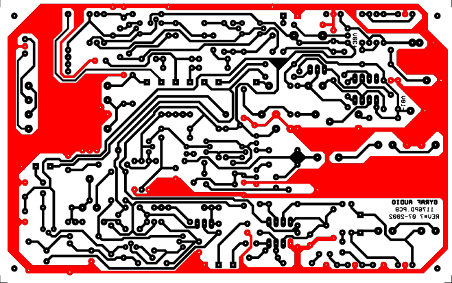
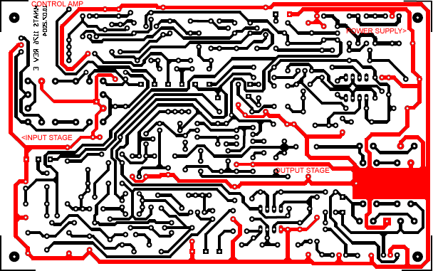
Can anyone explain in detail how changing the layout from the first image to the second can remove the hum experienced in the first circuit? Whis is there apparently a ground loop in the first and not the second? I would have thought that larger traces (first PCB) would be less prone to ground loops.
PCB with hum :

PCB with no hum :

The circuit is a UREI 1176 compressor clone. More info on this site.
PCB with hum :

PCB with no hum :

The circuit is a UREI 1176 compressor clone. More info on this site.
If you look at the top left of the old type board. There is a land next to it, (highest point and about 1/2" to the right where the ground copper narrows leaving the top left corner). Cut the ground just above the point where the first black vertical (C or hockey stick shaped black track) land and that will remove the "loop". Hope this helps.
I can't send an image as I can't get the page to accept a png file.
I can't send an image as I can't get the page to accept a png file.
As you can see, the ground (that's the red parts, right?) is running all the way around the edge of the board with hum. That's a big fat ground loop if I ever saw one. For the second board they changed to proper star grounding, and probably thought a little harder about grounding in general. In this case, topology wins over trace impedance hands down. Ideally you have both, but in audio you must get the topology right first. See e.g. LM317 wiring.
Cutting the offending ground at the top left corner as outlined should remove the hum, even if it looks like the second layout contains some other tweaks as well.
Cutting the offending ground at the top left corner as outlined should remove the hum, even if it looks like the second layout contains some other tweaks as well.
Here us the layout : http://mnats.net/files/1176Flayout.pdf
and the original schematic : http://www.gyraf.dk/gy_pd/1176/1176sch.gif
and the original schematic : http://www.gyraf.dk/gy_pd/1176/1176sch.gif
- Status
- This old topic is closed. If you want to reopen this topic, contact a moderator using the "Report Post" button.
- Home
- Source & Line
- Analog Line Level
- Ground Loop in UREI 1176 compressor