How CO2 phase behaviour can derail CCS projects
ValVestris
A world class energy consultancy firm, helping senior executives to get the big decisions right.
Summary: When compressing, injecting or transporting CO2 it is crucial that CO2 phase behaviour and Joule-Thomson effects are fully understood. With the help of a CO2 density calculator with phase indication we investigated what happens during an CO2 storage project in a depleted gas reservoir like the one currently being matured for offshore Netherlands. Three phases of CO2 are important in the pressure/temperature space for Carbon Capture and Storage, a high-density liquid phase, a low-density gas phase and a supercritical phase with higher densities approaching those of a liquid under high pressure but with the viscosity of a gas.
During transport of compressed CO2 from its source to an offshore storage reservoir, the CO2 passes through a pipeline at the seabed onto a platform and through wells into the subsurface. Two processes play a crucial role in CO2 transport, the cooling of the CO2 in the pipeline at the seabed and the pressure increase in the well between the well head and the storage reservoir. These processes have a significant impact on the CO2 phase behavior. They require a thorough understanding and special provisions to ensure that the CO2 enters the reservoir at the right pressure and temperature. When ignored, these density changes can have a major impact on the ability to inject CO2 into the reservoir or its containment.
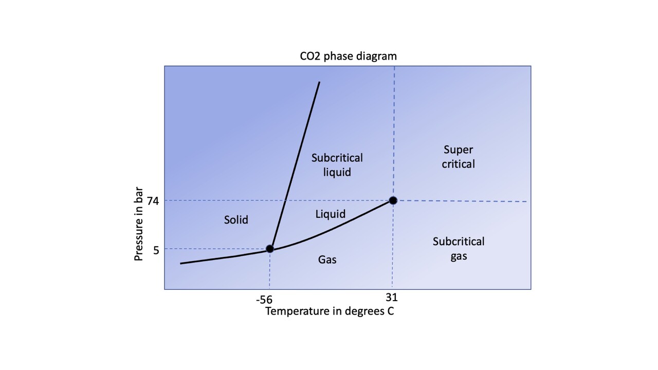
The CO2 phase diagram: CO2 is solid below the triple point between -78 degrees and -56 degrees Celsius at respectively 1 and 5 Bara When warming up under low pressure, the solid CO2 will turn into gas whilst under higher pressures (above 5-73 bar depending on the temperature) the solid CO2 will turn into a liquid.
More importantly for CCS, however, is the critical point at 31,1 Degrees C and 73,8 Bara between gas, liquid and a supercritical phase as these pressure and temperature boundaries will be likely be crossed during transport. These three distinct phases have vastly different properties with often sharp transitions.
Zooming in on the P and T conditions that are important for CO2 storage the above chart was refined using the CO2 density calculator (Fig. 1).

The dotted lines are iso-density lines and they show the very sharp density variations around the critical point moving from gas to liquid and from gas and liquid to the supercritical phase. These density variations go hand in hand with temperature effects such as strong cooling during pressure drop (moving from supercritical to gas) or heating up during compression.
A CO2 density cross section for a constant temperature of 40 degrees C and variable pressure is shown in Fig.2

Transition from liquid to supercritical phase with varying temperature is much more smoothly as shown in Fig. 3 for a density cross section at 200 Bara.

As hydrate formation during CO2 transport could also play a role hindering or disrupting gas transport, a hydrate formation envelope is included in Fig. 1 as a solid blue line. This will play a role in case of the presence of water in the gas or liquid CO2.
Impact on CO2 transport and storage:
CO2 injection in liquid phase: If we assume a situation with a reservoir at 3 km. depth that is heavily depleted down to say 20 Bara and CO2 is transported through a non-heated pipeline at a pressure above 75 Bara, that CO2 will reach a platform in liquid phase due to the cooling below 30 degrees C in the pipeline on the seabed. If that liquid CO2 with a fluid density of around 0.9 is directly injected into a depleted reservoir, this will occur at a very high pressure and overbalance due to the weight of the liquid CO2 column in a 3 km. deep well. This high overbalance and resulting expansion once it reaches the reservoir will cause a strong cooling effect (Joule-Thomson) at or near the perforations where liquid CO2 transforms back to gas due to the low reservoir pressure. Due to the rapid expansion and associated cooling, thermal fraccing as well as freezing of water that is likely to be present in the reservoir could cause severe reservoir and seal damage and potential loss of injectivity. Hence for low initial reservoir pressures below 75 Bara, injection should commence with CO2 in the gas phase.
CO2 Injection in gas phase: When CO2 is injected in the gas phase such a high overbalance is prevented. As we see from the phase diagram for pipeline transport this can only be achieved at relatively low pressures. The 4 step process of transporting low pressure CO2 in gas phase from source into reservoir in pressure and temperature space is depicted in Fig. 4 by the red line. This involves compression at the source (step 1), cooling and some pressure drop during transport in the pipeline (step 2), possibly a further pressure drop at the platform to avoid crossing a phase boundary in the well (3) and transport in the well from wellhead to perforations and further into the reservoir (4).

It is worth noting that with slightly higher pressures this profile comes close to the hydrate formation envelope and the phase boundary due to cooling in the pipeline and during expansion on the platform. The pressure drop (and expansion) at the platform helps to avoid the CO2 approaching the phase boundary with the supercritical phase in the completion assuming some warming up of the CO2 in the well.
With rising reservoir pressure due to injection, CO2 injection pressures will have to increase as well. This can be done for a brief period in the gas phase by reducing the CO2 expansion at the platform. When pipeline pressure is increased this process brings the injected CO2 even closer to the phase boundary and the hydrate envelope. This can only be done with dry CO2 and careful pressure control to avoid multi-phase flow whereby the base of the well bore around the perforations is most at risk. This is shown in Fig. 5 by the orange dashed line for a 50 Bara reservoir pressure (orange circle).

Injecting in liquid or supercritical phase in higher pressured reservoirs: when the reservoir pressure approaches 75 Bara it is clear that CO2 can no longer be injected in a gas phase as at higher pressures the CO2 is either in liquid or super critical phase. As mentioned earlier, injection in a liquid phase causes that large overbalance problem in the wells (Fig. 6, dashed line A in relation to the black circle), whereas injection in a super critical phase requires the CO2 to be heated.
There are 2 options to reduce the impact, both of them costly.
1) For non-heated pipelines and therefore transport in the liquid phase, this requires heating the liquid CO2 on the platform to some 70 degrees C thereby lowering the density through and bringing the CO2 into a supercritical phase as shown in Fig. 6, solid line B.
2) However, many offshore injection platforms may not have the facility to heat the CO2. In the case of pipeline transport for supercritical CO2, heating onshore is required as well as a transport pressure above 75 Bara and most importantly pipeline insulation and heating during transport. This is depicted in Fig. 6 by the dashed line C.

A third possibility would be to transport the CO2 initially in the gas phase through a non-heated pipeline and when the storage reservoir pressure approaches 75 Bara to transport the CO2 in (heated) supercritical phase by ship to avoid the CO2 cooling in the pipeline.
Conclusion:
When considering CO2 storage in a depleted gas reservoir the CO2 phase behaviour during the entire process needs to be thoroughly understood and the impact on the reservoir needs to be controlled and minimised. Even then, the exact timing and location of CO2 phase changes (and thereby the Joule-Thomson effect) in the completion or the injected reservoir area will remain hard to predict. Minimising these effects can either be through heating of pipelines or on platforms or transport by heated ships. Alternatively, one could either decide to limit the re-pressurising of the reservoir to below 75 Bara or re-pressurise the reservoir above 75 Bara ahead of CO2 injection.
When reservoir presure at the start of the CO2 injection is significantly higher, such as with injection into a reservoir with limited depletion or directly into a saline aquifer, these problems described above do not occur. However, these traps tend to have less storage space per sq. km. and/or may be less reliable in terms of long-term containment.
Depleted gas reservoirs that are most suitable for CO2 injection are those that are:
- close to onshore compression facilities to reduce the heated pipeline costs or
- have a relatively high pressure at the end of production or
- have a large storage space (thick and/or very extensive reservoirs) to warrant the high costs of additional heating
ValVestris with its surface and subsurface experience gained from the oil and gas industry coupled with its CCS feasibility experience is well positioned to assist potential clients with choosing the most appropriate reservoirs for CCS whilst considering the trade-offs between costs and storage potential.
Sources: https://www.intechopen.com/books/carbon-capture/phase-equilibria-for-carbon-capture-and-storage and https://blog.sintef.com/sintefenergy/ccs/CO2-mixture-property-knowledge-needed/
Project and Assurance Manager | Value Management | Complex technical and joint venture governance | Energy Front End Projects
9moExcellent summary, very enlightening
Experienced leader in oil & gas - development planning and project delivery
1yGood summary of some of the challenges in dealing with CO2 into depleted hydrocarbon reservoirs.