PROFIBUS-DP Communication Module - Yokogawa
PROFIBUS-DP Communication Module - Yokogawa
PROFIBUS-DP Communication Module - Yokogawa

Create successful ePaper yourself
Turn your PDF publications into a flip-book with our unique Google optimized e-Paper software.
General<br />
Specifications<br />
GS 34P02Q57-01E<br />
NFLP121<br />
<strong>PROFIBUS</strong>-<strong>DP</strong><br />
<strong>Communication</strong> <strong>Module</strong><br />
� GENERAL<br />
This General Specification (GS) describes <strong>PROFIBUS</strong>-<strong>DP</strong> communication functions and hardware specifications of<br />
the module.<br />
The <strong>PROFIBUS</strong>-<strong>DP</strong> <strong>Communication</strong> <strong>Module</strong> is installed in the FCN or FCN-RTU and communicates with the<br />
devices that have <strong>PROFIBUS</strong>-<strong>DP</strong> communication functionality.<br />
For details on FCN, see “FCN Autonomous Controller Hardware” (GS 34P02Q12-01E) and “FCN/FCJ Autonomous<br />
Controller Functions” (GS 34P02Q01-01E).For details on FCN-RTU, see “FCN-RTU Low Power Autonomous<br />
Controller Hardware” (GS 34P02Q13-01E) and “FCN-RTU Low Power Autonomous Controller Functions” (GS<br />
34P02Q02-01E).<br />
� FEATURES OF THE <strong>PROFIBUS</strong>-<strong>DP</strong> COMMUNICATION<br />
Specifications of the <strong>PROFIBUS</strong>-<strong>DP</strong> has been standardized internationally by the association of Profibus, and has<br />
been approved in the fieldbus international standard IEC61158 and European standard EN50170.<br />
<strong>PROFIBUS</strong>-<strong>DP</strong> has been used for communication with automation systems and distributed devices (remote I/O,<br />
inverters, etc.).<br />
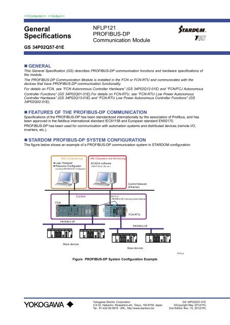
� STARDOM <strong>PROFIBUS</strong>-<strong>DP</strong> SYSTEM CONFIGURATION<br />
The figure below shows an example of a <strong>PROFIBUS</strong>-<strong>DP</strong> communication system in STARDOM configuration:<br />
ENG (Engineering)<br />
● Logic Designer<br />
● Resource Configurator<br />
(Including <strong>PROFIBUS</strong>-<strong>DP</strong> Configurator)<br />
FCN<br />
�����������<br />
Slave devices<br />
Control<br />
HMI (Operation and Monitoring)<br />
SCADA software<br />
(FAST/TOOLS, VDS, etc.)<br />
Control Network<br />
(Ethernet)<br />
�������<br />
���������������������������������<br />
FCN-RTU<br />
�����������<br />
Slave devices<br />
Figure <strong>PROFIBUS</strong>-<strong>DP</strong> System Configuration Example<br />
<strong>Yokogawa</strong> Electric Corporation<br />
2-9-32, Nakacho, Musashino-shi, Tokyo, 180-8750 Japan<br />
Tel.: 81-422-52-5616 URL: http://www.stardom.biz<br />
F01E.ai<br />
GS 34P02Q57-01E<br />
©Copyright May 2012(YK)<br />
2nd Edition Nov. 15, 2012(YK)
� FCN, FCN-RTU (FCN: STYLE S3 or later, FCN-RTU: STYLE S2 or later)<br />
FCN and FCN-RTU controls and monitors slave devices. It collects system alarms and other information from slave<br />
devices. Its control and calculation functions allow calculation results to be sent to slave devices.<br />
� <strong>PROFIBUS</strong>-<strong>DP</strong> <strong>Communication</strong> <strong>Module</strong> (NFLP121)<br />
The <strong>PROFIBUS</strong>-<strong>DP</strong> <strong>Communication</strong> <strong>Module</strong> is installed in the FCN or FCN-RTU system to provide for <strong>PROFIBUS</strong>-<strong>DP</strong><br />
communications. It runs as a master device in <strong>PROFIBUS</strong>-<strong>DP</strong> communication.<br />
� Logic Designer<br />
Logic Designer software is used for developing control applications for the FCN and FCN-RTU.<br />
It is used to create, debug, and download control applications to be run on the FCN and FCN-RTU.<br />
� Resource Configurator (Including <strong>PROFIBUS</strong>-<strong>DP</strong> Configurator)<br />
Resource Configurator software is used for basic FCN and FCN-RTU setup. It is used for basic configuration (IP<br />
address, I/O modules, license, and etc.) of the FCN and FCN-RTU and device label definition.<br />
From Resource Configurator, you can run the <strong>PROFIBUS</strong>-<strong>DP</strong> Configurator software tool.<br />
<strong>PROFIBUS</strong>-<strong>DP</strong> configurator is used for basic configuration of the <strong>PROFIBUS</strong>-<strong>DP</strong> (transmission rate, etc.), the slave<br />
device configuration, and module definitions and parameter settings in the slave device.<br />
� SCADA software (FAST/TOOLS, VDS and etc.)<br />
SCADA software is used for controlling and monitoring processes. SCADA software controls and monitors slave<br />
devices via the FCN or FCN-RTU.<br />
� Slave devices<br />
<strong>PROFIBUS</strong>-<strong>DP</strong> slave devices have <strong>PROFIBUS</strong>-<strong>DP</strong> communication functionality and thus can exchange data with the<br />
FCN or FCN-RTU connected to same <strong>PROFIBUS</strong>-<strong>DP</strong> via a <strong>PROFIBUS</strong>-<strong>DP</strong> <strong>Communication</strong> <strong>Module</strong> (NFLP121).<br />
All Rights Reserved. Copyright © 2012, <strong>Yokogawa</strong> Electric Corporation<br />
2<br />
GS 34P02Q57-01E May 31, 2012-00
� STARDOM <strong>PROFIBUS</strong>-<strong>DP</strong> SYSTEM MAIN FUNCTION<br />
The main function of a <strong>PROFIBUS</strong>-<strong>DP</strong> system is described below.<br />
� <strong>Communication</strong> and control functions<br />
The <strong>PROFIBUS</strong>-<strong>DP</strong> <strong>Communication</strong> <strong>Module</strong> (NFLP121) runs as <strong>PROFIBUS</strong>-<strong>DP</strong> master device.<br />
It supports two specification versions, namely, <strong>DP</strong>-V0 and <strong>DP</strong>-V1, and has the following communication and control<br />
functions.<br />
• Process data input and output: Control loops can be implemented using I/O data processing POUs for <strong>PROFIBUS</strong>-<br />
<strong>DP</strong> and device labels defined for I/O devices.<br />
• Message display: Diagnostic information detected by the <strong>PROFIBUS</strong>-<strong>DP</strong> <strong>Communication</strong> <strong>Module</strong> (NFLP121)<br />
or slave devices can be displayed on HMI (for operation and monitoring) as messages. Messages of the <strong>DP</strong>-V1<br />
specification can also be displayed for slave devices supporting the <strong>DP</strong>-V1 specification.<br />
• I/O module status display: Errors of the <strong>PROFIBUS</strong>-<strong>DP</strong> <strong>Communication</strong> <strong>Module</strong> (NFLP121) or other <strong>PROFIBUS</strong>-<strong>DP</strong><br />
communication errors can be displayed on HMI (for operation and monitoring).<br />
� System Specification<br />
Item Specification<br />
Number of installed NFLP121 modules<br />
4 max. for FCN (*1)<br />
2 max. for FCN-RTU<br />
Number of slave devices<br />
123 max. per module (if repeaters are used)<br />
31 max. per module (if no repeaters are used)<br />
Number of device labels (*2)<br />
255 max. per slave device<br />
500 max. per module<br />
<strong>Communication</strong> I/O data size 3072 words max. per module (*3)<br />
Number of communication I/O definitions 200 max. per module (*4)<br />
<strong>Communication</strong> capacity<br />
244 bytes max. for cyclic communications<br />
240 bytes max. for acyclic communications<br />
Transmission rate 9.6, 19.2, 45.45, 93.75, 187.5, 500, 1500, 3000, 6000, 12000 kbps<br />
*1: The number of NFLP121 modules allowed may be reduced if other communication modules are also installed.<br />
For details, see “FCN Autonomous Controller Hardware” (GS 34P02Q12-01E).<br />
*2: Total channel number of slave modules. All channels are counted up even they are not in use.<br />
*3: Minimum communication I/O data size is 2 words. No allocation limit for input data size and output data size.<br />
Maximum 1536 words can be assigned for holding output data.<br />
*4: Total number of modules in salve devices. Input/output mixed module is counted as two I/O definitions.<br />
All Rights Reserved. Copyright © 2012, <strong>Yokogawa</strong> Electric Corporation GS 34P02Q57-01E Nov. 15, 2012-00<br />
3
� ENGINEERING<br />
The Resource Configurator, <strong>PROFIBUS</strong>-<strong>DP</strong> Configurator and Logic Designer software tools are used in system<br />
engineering.<br />
All Rights Reserved. Copyright © 2012, <strong>Yokogawa</strong> Electric Corporation<br />
Table List of Engineering Software<br />
Software Description<br />
Resource Configurator Configuring <strong>PROFIBUS</strong>-<strong>DP</strong> <strong>Communication</strong> <strong>Module</strong> (NFLP121) and other I/O modules<br />
Starting <strong>PROFIBUS</strong>-<strong>DP</strong> Configurator<br />
Downloading FCN or FCN-RTU configuration information and <strong>PROFIBUS</strong>-<strong>DP</strong> Configurator<br />
configuration information.<br />
<strong>PROFIBUS</strong>-<strong>DP</strong> Configurator Registering slave devices<br />
Configuring <strong>PROFIBUS</strong>-<strong>DP</strong> communication protocol<br />
Logic Designer Defining device label variables<br />
ICreating control applications<br />
Downloading control applications<br />
� Engineering Scope<br />
The following shows the scope and targets for <strong>PROFIBUS</strong> engineering.<br />
VDS or<br />
FAST/TOOLS<br />
FCN or<br />
FCN-RTU<br />
NFLP121<br />
Slave<br />
Devices<br />
FCN or<br />
FCN-RTU<br />
Slave<br />
Devices<br />
Area engineered using<br />
Resource Configurator<br />
Figure Engineering Scope<br />
Area engineered using<br />
<strong>PROFIBUS</strong>-<strong>DP</strong> Configurator<br />
F02E.ai<br />
4<br />
GS 34P02Q57-01E May 31, 2012-00
� SOFTWARE AND LICENSE<br />
� Operating Environment<br />
The <strong>PROFIBUS</strong>-<strong>DP</strong> Configurator runs on the Windows 7 Professional SP1 (32 bit version only) operating system.<br />
The other system requirements are the same as those of the Logic Designer.<br />
Note: For details on the system requirements of Logic Designer, see “NT751FJ Logic Designer” (GS 34P02Q75-01E).<br />
� Software and License Required<br />
<strong>PROFIBUS</strong>-<strong>DP</strong> systems configuration requires the following software and licenses.<br />
Table Software and License Required<br />
Software Rev. No. License<br />
Resource Configurator<br />
(Including <strong>PROFIBUS</strong>-<strong>DP</strong> Configurator)<br />
R3.20.01 or later Not required<br />
Logic Designer R3.20.01 or later Required (*1)<br />
(Model: NT751FJ)<br />
PAS Portfolio R3.20.01 or later Required (*2)<br />
(Model: NT8001J)<br />
FCN/FCJ Basic Software License R3.20.01 or later Required (*3)<br />
(Model: NT711AJ, NT712AJ)<br />
Note: Refer to related GS for other software revisions and licenses.<br />
*1: A license code must be entered when installing the software on an engineering PC.<br />
*2: One execution license is required for each FCN. The license must be registered on FCN.<br />
No license is needed for using the Input/Output Data Processing POUs.<br />
*3: FCN-RTU basic software license (NT711AJ) is bundled with CPU modules.<br />
All Rights Reserved. Copyright © 2012, <strong>Yokogawa</strong> Electric Corporation GS 34P02Q57-01E May 31, 2012-00<br />
5
� HARDWARE SPECIFICATIONS<br />
Hardware specifications for NFLP121 <strong>PROFIBUS</strong>-<strong>DP</strong> communication module are as shown below.<br />
� SPECIFICATIONS<br />
Item Specification<br />
Model NFLP121<br />
Interface <strong>PROFIBUS</strong>-<strong>DP</strong><br />
Connection method EIA-RS485-Compliant<br />
Number of port 1<br />
Isolation Between signal and system<br />
Connector D-sub 9-pin female<br />
Maximum transmission distance 1.2 km/segment 9600 bps<br />
Maximum current consumption 700 mA 5V DC<br />
Weight 0.3 kg<br />
Note: The cables and terminators must comply with <strong>PROFIBUS</strong>-<strong>DP</strong> standards (<strong>PROFIBUS</strong> Specifications IEC61158-2 type3).<br />
All Rights Reserved. Copyright © 2012, <strong>Yokogawa</strong> Electric Corporation<br />
Table Connectors (D-sub 9-pin, female) (*1)<br />
Pin No Signal Name Function<br />
1 Shield Shield<br />
2 – Not used<br />
3 RxD/TxD-P Data reception/ transmission<br />
4 – Not used<br />
5 DGND Signal ground<br />
6 VP +5 V<br />
7 – Not used<br />
8 /TxD-N Data reception/ transmission<br />
9 – Not used<br />
*1: Connectors are fastened using inch screw threads (No.4-40UNC).<br />
5<br />
9<br />
4<br />
8<br />
3<br />
7<br />
2<br />
6<br />
1<br />
F03E.ai<br />
Figure Pin No. of D-sub 9-pin Connectors on the <strong>Module</strong><br />
6<br />
GS 34P02Q57-01E May 31, 2012-00
� MODEL AND SUFFIX CODES<br />
Model NFLP121 <strong>PROFIBUS</strong>-<strong>DP</strong> <strong>Communication</strong> <strong>Module</strong><br />
-S Standard type<br />
Suffix Code<br />
0<br />
0<br />
Always 0<br />
Basic type<br />
1 With ISA Standard G3 option<br />
All Rights Reserved. Copyright © 2012, <strong>Yokogawa</strong> Electric Corporation<br />
Subject to change without notice.<br />
Description<br />
� RELATED DOCUMENTS<br />
FCN/FCJ Autonomous Controller Functions GS 34P02Q01-01E<br />
FCN Autonomous Controller Hardware GS 34P02Q12-01E<br />
Logic Designer GS 34P02Q75-01E<br />
Application Portfolios for FCN/FCJ GS 34P02P20-01E<br />
VDS GS 34P02A02-01E<br />
FCN-RTU Low Power Autonomous Controller Functions GS 34P02Q02-01E<br />
FCN-RTU Low Power Autonomous Controller Hardware GS 34P02Q13-01E<br />
FAST/TOOLS GS 50A01A10-01EN<br />
� RESTRICTIONS AND PRECAUTIONS ON INSTALLATION<br />
• When you install these I/O modules, ensure that the total required power does not exceed the rated output of the<br />
power supply module used.<br />
• For further restrictions and precautions for module installation, see “FCN/FCJ Installation Guide” (TI 34P02Q91-<br />
01E).<br />
� ORDERING INFORMATION<br />
Specify the model and suffix codes.<br />
� TRADEMARKS<br />
• STARDOM is a trademark of <strong>Yokogawa</strong> Electric Corporation.<br />
• Other company names and product names in this document are registered trademarks or trademarks of their<br />
respective holders.<br />
8<br />
GS 34P02Q57-01E May 31, 2012-00