EP1894553A1 - Adjustable shower- and toilet chair - Google Patents
Adjustable shower- and toilet chair Download PDFInfo
- Publication number
- EP1894553A1 EP1894553A1 EP06018378A EP06018378A EP1894553A1 EP 1894553 A1 EP1894553 A1 EP 1894553A1 EP 06018378 A EP06018378 A EP 06018378A EP 06018378 A EP06018378 A EP 06018378A EP 1894553 A1 EP1894553 A1 EP 1894553A1
- Authority
- EP
- European Patent Office
- Prior art keywords
- chair
- frame
- backrest
- head support
- tube
- Prior art date
- Legal status (The legal status is an assumption and is not a legal conclusion. Google has not performed a legal analysis and makes no representation as to the accuracy of the status listed.)
- Granted
Links
- 230000007246 mechanism Effects 0.000 claims description 17
- 230000005540 biological transmission Effects 0.000 claims description 6
- 230000008878 coupling Effects 0.000 claims description 3
- 238000010168 coupling process Methods 0.000 claims description 3
- 238000005859 coupling reaction Methods 0.000 claims description 3
- 238000010276 construction Methods 0.000 description 5
- 230000005484 gravity Effects 0.000 description 5
- 230000008901 benefit Effects 0.000 description 4
- 230000006870 function Effects 0.000 description 4
- 230000035807 sensation Effects 0.000 description 2
- 238000005406 washing Methods 0.000 description 2
- 230000000712 assembly Effects 0.000 description 1
- 238000000429 assembly Methods 0.000 description 1
- 238000006243 chemical reaction Methods 0.000 description 1
- 238000004140 cleaning Methods 0.000 description 1
- 239000013065 commercial product Substances 0.000 description 1
- 238000006073 displacement reaction Methods 0.000 description 1
- 230000003670 easy-to-clean Effects 0.000 description 1
- 238000009429 electrical wiring Methods 0.000 description 1
- 238000004519 manufacturing process Methods 0.000 description 1
- 230000004048 modification Effects 0.000 description 1
- 238000012986 modification Methods 0.000 description 1
Images


Classifications
-
- A—HUMAN NECESSITIES
- A61—MEDICAL OR VETERINARY SCIENCE; HYGIENE
- A61G—TRANSPORT, PERSONAL CONVEYANCES, OR ACCOMMODATION SPECIALLY ADAPTED FOR PATIENTS OR DISABLED PERSONS; OPERATING TABLES OR CHAIRS; CHAIRS FOR DENTISTRY; FUNERAL DEVICES
- A61G5/00—Chairs or personal conveyances specially adapted for patients or disabled persons, e.g. wheelchairs
- A61G5/10—Parts, details or accessories
- A61G5/1002—Parts, details or accessories with toilet facilities
-
- A—HUMAN NECESSITIES
- A61—MEDICAL OR VETERINARY SCIENCE; HYGIENE
- A61G—TRANSPORT, PERSONAL CONVEYANCES, OR ACCOMMODATION SPECIALLY ADAPTED FOR PATIENTS OR DISABLED PERSONS; OPERATING TABLES OR CHAIRS; CHAIRS FOR DENTISTRY; FUNERAL DEVICES
- A61G5/00—Chairs or personal conveyances specially adapted for patients or disabled persons, e.g. wheelchairs
- A61G5/10—Parts, details or accessories
- A61G5/1056—Arrangements for adjusting the seat
- A61G5/1059—Arrangements for adjusting the seat adjusting the height of the seat
-
- A—HUMAN NECESSITIES
- A61—MEDICAL OR VETERINARY SCIENCE; HYGIENE
- A61G—TRANSPORT, PERSONAL CONVEYANCES, OR ACCOMMODATION SPECIALLY ADAPTED FOR PATIENTS OR DISABLED PERSONS; OPERATING TABLES OR CHAIRS; CHAIRS FOR DENTISTRY; FUNERAL DEVICES
- A61G5/00—Chairs or personal conveyances specially adapted for patients or disabled persons, e.g. wheelchairs
- A61G5/10—Parts, details or accessories
- A61G5/1056—Arrangements for adjusting the seat
- A61G5/1075—Arrangements for adjusting the seat tilting the whole seat backwards
-
- A—HUMAN NECESSITIES
- A61—MEDICAL OR VETERINARY SCIENCE; HYGIENE
- A61G—TRANSPORT, PERSONAL CONVEYANCES, OR ACCOMMODATION SPECIALLY ADAPTED FOR PATIENTS OR DISABLED PERSONS; OPERATING TABLES OR CHAIRS; CHAIRS FOR DENTISTRY; FUNERAL DEVICES
- A61G5/00—Chairs or personal conveyances specially adapted for patients or disabled persons, e.g. wheelchairs
- A61G5/10—Parts, details or accessories
- A61G5/12—Rests specially adapted therefor, e.g. for the head or the feet
- A61G5/121—Rests specially adapted therefor, e.g. for the head or the feet for head or neck
-
- A—HUMAN NECESSITIES
- A61—MEDICAL OR VETERINARY SCIENCE; HYGIENE
- A61G—TRANSPORT, PERSONAL CONVEYANCES, OR ACCOMMODATION SPECIALLY ADAPTED FOR PATIENTS OR DISABLED PERSONS; OPERATING TABLES OR CHAIRS; CHAIRS FOR DENTISTRY; FUNERAL DEVICES
- A61G5/00—Chairs or personal conveyances specially adapted for patients or disabled persons, e.g. wheelchairs
- A61G5/10—Parts, details or accessories
- A61G5/12—Rests specially adapted therefor, e.g. for the head or the feet
- A61G5/128—Rests specially adapted therefor, e.g. for the head or the feet for feet
Definitions
- the invention relates to a shower and toilet chair, particularly suitable for disabled persons, comprising a support frame provided with means with which it can support on the ground, a secondary frame which bears a seat and a backrest, which support frame and which secondary frame respectively carry on either side at least a first frame tube and at least a second frame tube which are slidable into each other as a telescopic guiding for the purpose of height adjustment of the secondary frame.
- Such a shower/toilet chair is known from the German Gebrauchsmusterschrift DE 202 18 195 U1 . Described herein is a height-adjustable, mobile shower chair in which the telescopically operating height adjustment consists of two sets of tubes, of which the one set are tubes slidable in and out of each other by means of a drive and the other set only provide the guiding.
- the sets of tubes of this known adjusting mechanism are however located in this known chair in the space directly beneath the sides of the chair seat, so on the side of the backrest directed toward the seat.
- This chair hereby has inconvenient obstacles between the chair seat and the longitudinal bars connecting the wheels.
- the invention has for its object to provide a shower/toilet chair as according to the preamble which, while retaining essentially the same functionality, has no inconvenient obstacles under the sides of the chair seat and can take a compact form.
- the frame tubes extend on the side of the support surface of the backrest remote from the chair seat, and in that drive means are present in the telescopic frame tubes for the purpose of adjusting the height of the shower/toilet chair by telescopic sliding of the frame tubes.
- the shower/toilet chair is easy to clean and has an aesthetically pleasing appearance.
- Both the function of raising and lowering the secondary frame when adjusting the height of the chair and the function of guiding the secondary frame during the height adjustment are preferably carried out by the frame tubes of the telescopic guiding.
- the frame tubes are therefore embodied so as to form the only load-bearing coupling between the support frame and the secondary frame.
- the frame tubes extend on either side of the backrest, which enhances the stability during raising and lowering of the secondary frame.
- each second frame tube is connected at its upper end to the secondary frame by means of a pivoting connection.
- the secondary frame of the shower/toilet chair with seat and backrest can be tilted rearward in any height position, so that a person standing next to the chair can easily wash the hair of and attend to the feet of a person sitting in the chair.
- each second frame tube and the secondary frame are situated close to the top side of the backrest, and extending rods are mounted between respectively one of the front corner points of the chair seat and one of the lower ends of the second frame tubes, and drive means are present for tilting the shower/toilet chair by telescopically sliding the frame tubes.
- this achieves that the centre of gravity of the chair is displaced to a higher position slightly to the rear during the telescopic adjustment, thus forming a compensation for the forward displacement of the centre of gravity during rearward tilting of the chair via pivoting about the upper side of the backrest.
- This has the advantage that the distance between the front and the rear wheels can remain limited without the risk that the chair can fall over easily in its highest and/or tilted position.
- An alternative embodiment of a shower/toilet chair wherein the pivoting connections between each second frame tube and the secondary frame are situated close to the underside of the backrest, has the advantage that a shorter telescopic guiding is necessary, which enables the same height adjustment of the chair with the use of a telescopic guiding consisting of for instance three parts.
- Embodying the drive for the height adjustment of the chair as a linear actuator which can be operated by an electric motor achieves that the motor can be concealed in the backrest or in the upper part of the second frame tubes so that, particularly in the latter case, a very good watertight seal is possible in simple manner.
- a relatively long arm is fixedly connected at an outer end to the rotation shaft about which the head support is rotatable
- a relatively short arm is rotatably connected at an outer end to a low-lying part of the backrest
- the other outer ends of the long and short arm are connected rotatably to each other at a rotation point lying on the side, remote from the backrest, of the plane passing through the rotation shaft of the head support and the fastening point of the short arm to the backrest.
- the head support 11 tilts less far to the rear (for instance 20°) than the rest of the chair (for instance 30°). This is to ensure that a person sitting in the chair does not have the feeling of falling backwards when the chair is tilted rearward.
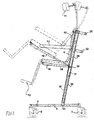
- Figure 1 shows a height-adjustable and tiltable shower chair which can also be used as a toilet chair in the shown, non-adjusted situation.
- the chair consists of two frames, a support frame 1 and a secondary frame 2.
- Support frame 1 comprises two tubular longitudinal bars 3 which are mutually connected at their front ends by means of a likewise tubular crossbar 4.
- Longitudinal bars 3 bear swivel wheels 6 at their front ends and swivel wheels 7 at their rear ends.
- Crossbar 4 is situated as far to the front of the chair as possible so as to enable unimpeded sliding of longitudinal bars 3 along the toilet bowl during use as a toilet chair.
- Secondary frame 2 is formed substantially by a tube frame 8 to which a chair seat 9 and a backrest 10 are fixed.
- a head support 11, two footrests 12 and two armrests 13 are further fixed to tube frame 8.
- each tube 15 Fixed onto each of longitudinal bars 3 of support frame 1 is a tube 15 which protrudes upward while inclining slightly to the rear. As seen from the front side of the chair, the point of attachment 14 lies beyond the centre of longitudinal bars 3. Dropping round each tube 15 is a tube 16, which forms a telescopic guiding together with tube 15. At their top outer ends tubes 16 are fixed to tube frame 8 of secondary frame 2 on either side of the upper edge of backrest 10.
- a per se known linear actuator 17 is arranged inside each set of tubes 15 and 16 slidable into each other as a telescopic guiding.
- Such an actuator comprises a spindle in the one tube which co-acts with a nut in the other tube.
- An electric motor for rotating the spindle can be incorporated in the backrest or, in a very compact embodiment, in the upper part of each tube 16.
- Linear actuators are a normal commercial product, for instance type LA 22 from the firm LINAK, for forming a compact construction for the direct conversion of a rotating movement to a linear movement, and do not therefore require detailed explanation.
- Actuator 17 consists of three main components: motor, gear transmission and spindle including nut. The spindle part and the nut form the heart of actuator 17. The transmission transmits the rotation movement of the motor to the spindle.
- Extending rod assemblies consisting of two tubes 18 and 19 sliding telescopically into each other are mounted under each side of chair seat 9 for the purpose of tilting the chair rearward.
- Tube 18 is mounted at an outer end on tube frame 8 of secondary frame 2 under one of the front corner points of chair seat 9.
- Tubes 19 are each mounted at their free end on one of the lower ends of frame tubes 16.
- Each set of tubes 18,19 is embodied as a linear actuator (not shown) of the same type as actuator 17.
- brackets 21 and 22 connecting frame tubes 16 are arranged for moving the chair. These brackets also ensure a good stability of the chair in transverse direction.
- the upper bracket 21 is suitable for a somewhat taller operating person and lower bracket 22 for a somewhat shorter person and for allowing easy moving of the chair in its upwardly adjusted position.
- Figure 2 shows the chair in its lowest position. In this position a person can sit down in the chair and get out of the chair, and the chair can serve as toilet chair.
- the chair can also be tilted rearward (shown with broken lines), for instance in order to attend the feet of a person sitting in the chair.
- Figure 3 shows the chair in its highest position. In this position a person sitting in the chair can easily be helped during showering without the caring person having to bend. The latter is also the case when the chair is tilted rearward in the highest position (shown with broken lines), for instance for washing the hair of a person sitting in the chair.
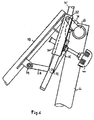
- FIG. 4-6 The details of an embodiment of a shower/toilet chair according to the invention shown in figures 4-6 relate to an adjustable head support 11 above backrest 10 of the chair.
- head support 11 tilts less far back (for instance 20') than the rest of the chair (for instance 30') when the chair is tilted rearward. This is to ensure that a person sitting in the chair does not get the feeling of falling backward when the chair is tilted rearward. This sensation is easily created when the head support tilts rearward to the same extent as the seat and backrest of the chair. Tilting the head support less far to the rear achieves according to the invention that the person sitting in the chair remains looking straight ahead more instead of at the ceiling, and is thus given less of a sensation of falling backward.
- FIG. 4 An example of a transmission mechanism 27 for achieving the above stated tilting of the head support is shown in figure 4.
- Figures 5 and 6 show a shower/toilet chair provided with such a mechanism in its extreme positions.
- This mechanism essentially consisting of a 4-rod mechanism, will now be described with reference to figure 4. It will be apparent that there are other mechanisms for realizing said tilting of the head support, for instance mechanisms with a different number of rods or a mechanism in which use is made of a gear transmission, these mechanisms all lying within the reach of the skilled person.
- a connecting rod 28 is mounted fixedly between upper outer ends of frame tubes 16. Connecting rod 28 forms the pivoting shaft between support frame 1 and secondary frame 2 for tilting the chair.
- Backrest 10 is fixed to a sub-frame 29.
- arms 30, which are mounted at their free ends with a bushing for rotation round the connecting rod 28 between second frame tubes 16.
- connecting rod 28 Fixed close to the centre of connecting rod 28 is a short arm 31 which protrudes obliquely upward in the direction of the top side of backrest 10 and has on its free end a round hole into which protrudes a pin 32 extending parallel to connecting rod 28.
- a collar 33 Fastened to pin 32 is a collar 33 which is fixedly connected to a tube 34 extending centrally between second frame tubes 16 in vertical direction.
- a rod 35 bearing head support 11 is received slidably in tube 34.
- Rod 35 fits into tube 34 with friction and can be displaced therein by hand for the purpose of manual height adjustment of the head support.
- a long arm 36 is further mounted for free rotation round pin 32.
- Arm 36 is fixedly connected to bush 33 so that tube 34 also rotates round pin 32 when arm 36 is rotated around pin 32.
- the free outer end of this arm 36 is connected to the outer end of a short arm 38 for free rotation about shaft 37.
- the other end 39 of this short arm 38 is connected in freely rotatably manner to a low-lying part of sub-frame 29 bearing backrest 10.
- Shaft 37 lies on the side, remote from backrest 10, of the plane passing through axes of rotation points 32 and 39.
- turning knob 40 connected to an adjusting mechanism the tube 34 can further be rotated about pin 32 for the purpose of manually tilting head support 11 forward or rearward.
- turning knob 40 carries a spindle with which the distance between the centre of long arm 36 and tube 34 can be changed independently of the automatic rotation of head support 11 during tilting of the chair.
- tube 34 will be rotated about pin 32 when turning knob 40 is rotated in order to adjust the initial tilt position of head support 11 relative to the rest of the chair or to adjust the tilt position of the head support after rearward tilting of the chair.
- the latter is for instance for the purpose of additional tilting of the head support to the rear in the rearward tilted showering position of the chair, so as to thus enable easier washing of the hair of a person sitting in the chair.
- the height of head support 11 can be adjusted without additional operating means by pulling pin 35 further out of tube 34 or pressing it further therein by means of a friction connection between tube 34 and pin 35.
- a shorter length of the telescopic guiding can be obtained by fixing the upper end thereof to secondary frame 2 close to the rear edge of seat 9. So as to still obtain a relatively long extended length with such a shorter pushed-in telescopic guiding, a telescopic guiding consisting of three parts may be necessary.
- Control means for the height adjustment and tilting of the shower/toilet chair according to the invention can be easily concealed in the backrest of the chair, wherein the electrical wiring of these control means can be readily concealed in the tubes of the chair. This is particularly the case for the motor for rearward tilting of the chair, which is situated in tubes 18 close to the front corners of chair seat 9. The wiring then runs via frame tubes 8 of secondary frame 2 and does not therefore have to span any variable distance.
- the open design of the construction is also advantageous for cleaning and keeping the chair clean. This greatly enhances hygiene.
Abstract
Description
- The invention relates to a shower and toilet chair, particularly suitable for disabled persons, comprising a support frame provided with means with which it can support on the ground, a secondary frame which bears a seat and a backrest, which support frame and which secondary frame respectively carry on either side at least a first frame tube and at least a second frame tube which are slidable into each other as a telescopic guiding for the purpose of height adjustment of the secondary frame.
- Such a shower/toilet chair is known from the German Gebrauchsmusterschrift
DE 202 18 195 U1 . Described herein is a height-adjustable, mobile shower chair in which the telescopically operating height adjustment consists of two sets of tubes, of which the one set are tubes slidable in and out of each other by means of a drive and the other set only provide the guiding. The sets of tubes of this known adjusting mechanism are however located in this known chair in the space directly beneath the sides of the chair seat, so on the side of the backrest directed toward the seat. This chair hereby has inconvenient obstacles between the chair seat and the longitudinal bars connecting the wheels. - The invention has for its object to provide a shower/toilet chair as according to the preamble which, while retaining essentially the same functionality, has no inconvenient obstacles under the sides of the chair seat and can take a compact form.
- This objective is achieved according to the invention in that the frame tubes extend on the side of the support surface of the backrest remote from the chair seat, and in that drive means are present in the telescopic frame tubes for the purpose of adjusting the height of the shower/toilet chair by telescopic sliding of the frame tubes.
- Hereby achieved is that no obstacles are present beneath the chair seat which may cause discomfort to a person sitting in the chair and/or a person caring for the person sitting in the chair. Also achieved is that, owing to its open nature, the shower/toilet chair is easy to clean and has an aesthetically pleasing appearance.
- Both the function of raising and lowering the secondary frame when adjusting the height of the chair and the function of guiding the secondary frame during the height adjustment are preferably carried out by the frame tubes of the telescopic guiding. In a particularly advantageous embodiment the frame tubes are therefore embodied so as to form the only load-bearing coupling between the support frame and the secondary frame. By combining the function of height adjustment of the secondary frame and the function of guiding the secondary frame during such a height adjustment, the construction can then be simpler and therefore cheaper to manufacture.
- In a further preferred embodiment the frame tubes extend on either side of the backrest, which enhances the stability during raising and lowering of the secondary frame.
- In an embodiment of a shower chair according to the invention each second frame tube is connected at its upper end to the secondary frame by means of a pivoting connection.
- This achieves that the secondary frame of the shower/toilet chair with seat and backrest can be tilted rearward in any height position, so that a person standing next to the chair can easily wash the hair of and attend to the feet of a person sitting in the chair.
- In an attractive embodiment of a rearward tiltable shower chair according to the invention the pivoting connections between each second frame tube and the secondary frame are situated close to the top side of the backrest, and extending rods are mounted between respectively one of the front corner points of the chair seat and one of the lower ends of the second frame tubes, and drive means are present for tilting the shower/toilet chair by telescopically sliding the frame tubes.
- This achieves that, during rearward tilting of the shower chair, the chair seat also moves upward over a relatively great distance so that the telescopic height adjustment of the chair can remain limited in order to achieve the same height position of the chair seat.
- In a further attractive embodiment according to the invention of a rearward tiltable shower chair, wherein the backrest already inclines slightly rearward when the chair is not in the rearward tilted position, the frame tubes which are telescopically slidable into each other extend in a plane parallel to the plane in which the backrest lies.
- In addition to an aesthetically pleasing positioning of the frame tubes, this achieves that the centre of gravity of the chair is displaced to a higher position slightly to the rear during the telescopic adjustment, thus forming a compensation for the forward displacement of the centre of gravity during rearward tilting of the chair via pivoting about the upper side of the backrest. This has the advantage that the distance between the front and the rear wheels can remain limited without the risk that the chair can fall over easily in its highest and/or tilted position.
- An alternative embodiment of a shower/toilet chair, wherein the pivoting connections between each second frame tube and the secondary frame are situated close to the underside of the backrest, has the advantage that a shorter telescopic guiding is necessary, which enables the same height adjustment of the chair with the use of a telescopic guiding consisting of for instance three parts.
- Embodying the drive for the height adjustment of the chair as a linear actuator which can be operated by an electric motor achieves that the motor can be concealed in the backrest or in the upper part of the second frame tubes so that, particularly in the latter case, a very good watertight seal is possible in simple manner.
- In another attractive embodiment of a shower/toilet chair according to the invention, wherein a head support is present and wherein the pivoting connection between each second frame tube and the secondary frame is situated close to the upper side of the backrest, the rotation shaft about which the head support is rotatable lies a short distance from said pivoting connection and closer to the support surface of the backrest, a relatively long arm is fixedly connected at an outer end to the rotation shaft about which the head support is rotatable, a relatively short arm is rotatably connected at an outer end to a low-lying part of the backrest, and the other outer ends of the long and short arm are connected rotatably to each other at a rotation point lying on the side, remote from the backrest, of the plane passing through the rotation shaft of the head support and the fastening point of the short arm to the backrest.
- This achieves that, when the chair is tilted rearward, the head support 11 tilts less far to the rear (for instance 20°) than the rest of the chair (for
instance 30°). This is to ensure that a person sitting in the chair does not have the feeling of falling backwards when the chair is tilted rearward. - Other features and advantages of the invention will be elucidated hereinbelow with reference to the accompanying drawings, in which:
- Fig. 1 shows an embodiment of a shower/toilet chair according to the invention in front/side perspective view in its lowest rest position,
- Fig. 2 is a side view of the shower/toilet chair according to Fig. 1 in its lowest position,
- Fig. 3 is a side view of the shower/toilet chair according to Fig. 1 in its highest position,
- Fig. 4 shows a perspective view of a detail of an embodiment of the coupling between the secondary frame and the base frame and an adjusting mechanism of the head support,
- Fig. 5 is a side view of the embodiment according to Fig. 4 in its non-tilted position, and
- Fig. 6 shows a side view of the embodiment according to Fig. 4 in a tilted position.
- Figure 1 shows a height-adjustable and tiltable shower chair which can also be used as a toilet chair in the shown, non-adjusted situation. The chair consists of two frames, a support frame 1 and a
secondary frame 2. - Support frame 1 comprises two tubular
longitudinal bars 3 which are mutually connected at their front ends by means of a likewise tubular crossbar 4.Longitudinal bars 3 bearswivel wheels 6 at their front ends andswivel wheels 7 at their rear ends. Crossbar 4 is situated as far to the front of the chair as possible so as to enable unimpeded sliding oflongitudinal bars 3 along the toilet bowl during use as a toilet chair. -
Secondary frame 2 is formed substantially by atube frame 8 to which a chair seat 9 and abackrest 10 are fixed. A head support 11, twofootrests 12 and twoarmrests 13 are further fixed totube frame 8. - The above description of the general construction of the shower/toilet chair is deemed sufficient to understand the type of chair to which the invention relates.
- Fixed onto each of
longitudinal bars 3 of support frame 1 is atube 15 which protrudes upward while inclining slightly to the rear. As seen from the front side of the chair, the point ofattachment 14 lies beyond the centre oflongitudinal bars 3. Dropping round eachtube 15 is atube 16, which forms a telescopic guiding together withtube 15. At their topouter ends tubes 16 are fixed totube frame 8 ofsecondary frame 2 on either side of the upper edge ofbackrest 10. A per se knownlinear actuator 17 is arranged inside each set oftubes tube 16. - In the latter case a watertight construction can be realized in simple manner, this of course being of great importance in the use as shower chair.
- Linear actuators are a normal commercial product, for
instance type LA 22 from the firm LINAK, for forming a compact construction for the direct conversion of a rotating movement to a linear movement, and do not therefore require detailed explanation.Actuator 17 consists of three main components: motor, gear transmission and spindle including nut. The spindle part and the nut form the heart ofactuator 17. The transmission transmits the rotation movement of the motor to the spindle. - Extending rod assemblies consisting of two
tubes tube frame 8 ofsecondary frame 2 under one of the front corner points of chair seat 9.Tubes 19 are each mounted at their free end on one of the lower ends offrame tubes 16. Each set oftubes actuator 17. - Two handles in the form of two
brackets frame tubes 16 are arranged for moving the chair. These brackets also ensure a good stability of the chair in transverse direction. Theupper bracket 21 is suitable for a somewhat taller operating person andlower bracket 22 for a somewhat shorter person and for allowing easy moving of the chair in its upwardly adjusted position. - Figure 2 shows the chair in its lowest position. In this position a person can sit down in the chair and get out of the chair, and the chair can serve as toilet chair. The chair can also be tilted rearward (shown with broken lines), for instance in order to attend the feet of a person sitting in the chair.
- Figure 3 shows the chair in its highest position. In this position a person sitting in the chair can easily be helped during showering without the caring person having to bend. The latter is also the case when the chair is tilted rearward in the highest position (shown with broken lines), for instance for washing the hair of a person sitting in the chair.
- The drive for the height adjustment and the tilting of the chair according to the invention will be further described hereinbelow.
- For the embodiment shown in the figures this will be done first with reference to figures 2 and 3.
- For the height adjustment use is made of electric motors which are located in the linear actuator inside
backrest 10 or insideframe tubes 16. - When the motor is activated the extending
parts actuators 17 move apart.Part 25 is mounted hingedly at its upper end inframe tube 16 andpart 26 is mounted hingedly at its lower end inframe tube 15. When actuators 17 extend the chair moves upward from the position shown in figure 2 to no further than the position shown in figure 3. The centre of gravity of the chair is displaced slightly here to the rear. - When the linear actuator formed by extending
rods secondary frame 2 of the chair rotates about the rotation point betweensecondary frame 2 andframe tubes 16 at the position of the top side ofbackrest 10. The chair herein rotates to the position shown with broken lines in figures 2 and 3, wherein the centre of gravity of the chair is displaced slightly to the front side of the chair. The high position of the rotation point during tilting also moves the chair seat upward, so that less than the normal height adjustment is necessary in order to reach the same height position. - When the rearward inclination of the frame tubes in combination with the maximum angular rotation of the chair during tilting are chosen such that the centres of gravity in the highest position of the chair in the tilted and non-tilted positions lie roughly equally far from a vertical plane lying centrally between
front wheels 6 andrear wheels 7, it is achieved that the stability of the chair is as great as possible with the smallest possible distance between front andrear wheels - An elegant alignment of the chair is also obtained by choosing the rearward inclining position of
frame tubes - The details of an embodiment of a shower/toilet chair according to the invention shown in figures 4-6 relate to an
adjustable head support 11 abovebackrest 10 of the chair. - According to an aspect of the present invention,
head support 11 tilts less far back (for instance 20') than the rest of the chair (for instance 30') when the chair is tilted rearward. This is to ensure that a person sitting in the chair does not get the feeling of falling backward when the chair is tilted rearward. This sensation is easily created when the head support tilts rearward to the same extent as the seat and backrest of the chair. Tilting the head support less far to the rear achieves according to the invention that the person sitting in the chair remains looking straight ahead more instead of at the ceiling, and is thus given less of a sensation of falling backward. - An example of a transmission mechanism 27 for achieving the above stated tilting of the head support is shown in figure 4. Figures 5 and 6 show a shower/toilet chair provided with such a mechanism in its extreme positions. This mechanism, essentially consisting of a 4-rod mechanism, will now be described with reference to figure 4. It will be apparent that there are other mechanisms for realizing said tilting of the head support, for instance mechanisms with a different number of rods or a mechanism in which use is made of a gear transmission, these mechanisms all lying within the reach of the skilled person.
- As can be clearly seen in figure 4, a connecting rod 28 is mounted fixedly between upper outer ends of
frame tubes 16. Connecting rod 28 forms the pivoting shaft between support frame 1 andsecondary frame 2 for tilting the chair. -
Backrest 10 is fixed to a sub-frame 29. Mounted on either side of this sub-frame arearms 30, which are mounted at their free ends with a bushing for rotation round the connecting rod 28 betweensecond frame tubes 16. - Fixed close to the centre of connecting rod 28 is a short arm 31 which protrudes obliquely upward in the direction of the top side of
backrest 10 and has on its free end a round hole into which protrudes a pin 32 extending parallel to connecting rod 28. Fastened to pin 32 is a collar 33 which is fixedly connected to a tube 34 extending centrally betweensecond frame tubes 16 in vertical direction. - A rod 35
bearing head support 11 is received slidably in tube 34. Rod 35 fits into tube 34 with friction and can be displaced therein by hand for the purpose of manual height adjustment of the head support. - A
long arm 36 is further mounted for free rotation round pin 32.Arm 36 is fixedly connected to bush 33 so that tube 34 also rotates round pin 32 whenarm 36 is rotated around pin 32. The free outer end of thisarm 36 is connected to the outer end of a short arm 38 for free rotation about shaft 37. Theother end 39 of this short arm 38 is connected in freely rotatably manner to a low-lying part of sub-frame 29 bearingbackrest 10. Shaft 37 lies on the side, remote frombackrest 10, of the plane passing through axes of rotation points 32 and 39. - Using a turning knob 40 connected to an adjusting mechanism the tube 34 can further be rotated about pin 32 for the purpose of manually tilting
head support 11 forward or rearward. For this purpose turning knob 40 carries a spindle with which the distance between the centre oflong arm 36 and tube 34 can be changed independently of the automatic rotation ofhead support 11 during tilting of the chair. - The operation of the mechanism shown in figures 4-6 is as follows:
- Upon rotation of
secondary frame 2 of the chair about the rotation axis formed by connecting rod 28 from the position shown in figure 5 to the position shown in figure 6 and back, sub-frame 29 ofbackrest 10 also rotates about this rotation axis. Theouter end 39 of short arm 38, which is fixed to sub-frame 29, herein describes an arc with the rotation axis of connecting rod 28 as centre, as if there were a direct arm connection between rod 28 andouter end 39 of arm 38. - As the
outer end 39 is displaced,arms 38 and 36 also co-rotate therewith, whereinarm 36 rotates about the outer end (pin 32) of arm 31. During rotation ofouter end 39 through a determined angle α (imaginary round rod 28)arm 36 rotates through an angle β about the end of arm 31, wherein β becomes increasingly smaller than α as the ratio between lengths ofarms 36 and 38 becomes smaller and/or the length of arm 31 becomes greater. Since during rotation of pin 33 through an angle β the tube 34 with the pin 35 withhead support 11 inserted therein also rotates through the same angle β, and β is smaller than α,head support 11 will automatically tilt less far to the rear than the chair during rearward tilting, and the opposite will happen during tilting back. In a determined preferred embodiment a suitable ratio between α and β lies between 1.0 and 2.0, and is preferably about 1.5, so that the head support tilts through about 20' when the chair is tilted through about 30°. - Independently of the above described, automatically operating adjustment of the head support, tube 34 will be rotated about pin 32 when turning knob 40 is rotated in order to adjust the initial tilt position of
head support 11 relative to the rest of the chair or to adjust the tilt position of the head support after rearward tilting of the chair. The latter is for instance for the purpose of additional tilting of the head support to the rear in the rearward tilted showering position of the chair, so as to thus enable easier washing of the hair of a person sitting in the chair. - Finally, the height of
head support 11 can be adjusted without additional operating means by pulling pin 35 further out of tube 34 or pressing it further therein by means of a friction connection between tube 34 and pin 35. - In an embodiment (not shown) of a shower/toilet chair according to the invention a shorter length of the telescopic guiding can be obtained by fixing the upper end thereof to
secondary frame 2 close to the rear edge of seat 9. So as to still obtain a relatively long extended length with such a shorter pushed-in telescopic guiding, a telescopic guiding consisting of three parts may be necessary. - Control means for the height adjustment and tilting of the shower/toilet chair according to the invention can be easily concealed in the backrest of the chair, wherein the electrical wiring of these control means can be readily concealed in the tubes of the chair. This is particularly the case for the motor for rearward tilting of the chair, which is situated in
tubes 18 close to the front corners of chair seat 9. The wiring then runs viaframe tubes 8 ofsecondary frame 2 and does not therefore have to span any variable distance. - One of the most striking advantages of the invention is the absence of components which could possibly get in the way. Only the telescopic guiding 15,16 is situated between base frame 1 and the essential components of the actual chair. Since this is placed far to the rear, there is little danger of a person sitting in the chair and an assisting person being inconvenienced by components getting in the way. This enhances safety.
- The open design of the construction is also advantageous for cleaning and keeping the chair clean. This greatly enhances hygiene.
- It will be apparent that only a few possible embodiments of a shower/toilet chair according to the invention are shown in the drawings and described above, and that many modifications can be made without departing from the scope of the present invention as stated in the appended claims.
Claims (22)
- Height-adjustable shower and toilet chair, particularly suitable for disabled persons, comprising a support frame (1) provided with means (6,7) with which it can support on the ground, a secondary frame (2) which bears a seat (9) and a backrest (11), which support frame (1) and which secondary frame (2) respectively carry on either side at least a first frame tube (15) and at least a second frame tube (16) which are slidable into each other as a telescopic guiding for the purpose of height adjustment of the secondary frame, characterized in that the frame tubes (15,16) extend on the side of the support surface of the backrest (10) remote from the chair seat (9), and that drive means (17) are present in the telescopic frame tubes (15,16) for the purpose of adjusting the height of the shower/toilet chair by telescopic sliding of the frame tubes (15,16).
- Chair as claimed in claim 1, wherein the frame tubes (15,16) are embodied so as to form the only load-bearing coupling between the support frame (1) and the secondary frame (2).
- Chair as claimed in claim 1 or 2, wherein the frame tubes (15,16) extend on either side of the backrest.
- Chair as claimed in claim 1, characterized in that each second frame tube (16) is connected at its upper end to the secondary frame (2,8) by means of a pivoting connection.
- Chair as claimed in claim 4, characterized in that the pivoting connections between each second frame tube (16) and the secondary frame (2,8) are situated close to the top side of the backrest (10), that extending rods (18,19) are mounted between respectively one of the front corner points of the chair seat (9) and one of the lower ends of the second frame tubes (16), and that drive means are present for tilting the shower/toilet chair by telescopically sliding the extending rods (18,19).
- Chair as claimed in claim 5, wherein the backrest (10) already inclines slightly rearward when the chair is not in the rearward tilted position, characterized in that the frame tubes (15,16) which are telescopically slidable into each other extend in a plane parallel to the plane in which the backrest (10) lies.
- Chair as claimed in claim 4, characterized in that the pivoting connections between each second frame tube (16) and the secondary frame (2,8) are situated close to the underside of the backrest (10).
- Chair as claimed in any of the foregoing claims, characterized in that the drive means in the frame tubes (15,16) telescopically slidable into each other are formed by a linear actuator (17:25,26) which can be operated by an electric motor.
- Chair as claimed in claim 8, characterized in that the electric motor is accommodated in the backrest (10).
- Chair as claimed in claim 8, characterized in that the electric motor is accommodated in the upper part of each of the second frame tubes (16).
- Chair as claimed in claim 5, characterized in that the telescopically slidable rods (18,19) are formed by a linear actuator which can be operated by an electric motor.
- Chair as claimed in any of the foregoing claims, characterized in that at least one handle (21) is present in the form of a bracket connecting the frame tubes.
- Chair as claimed in claim 12, characterized in that two handles (21,22) are present lying one above the other.
- Chair as claimed in any of the claims 3-13, comprising a head support (11) arranged above the backrest (10) and a transmission mechanism (27) arranged between the head support and the backrest for causing tilting of the head support relative to the backrest during tilting of the backrest.
- Chair as claimed in claim 14, wherein the transmission mechanism (27) is adapted to tilt the head support (11) relative to the backrest (10) in a pre-adjustable ratio.
- Chair as claimed in claim 14 or 15, wherein the mechanism is adapted to tilt the head support and backrest in a ratio between the angular rotation of the backrest (10) and of the head support (11) in the range of 1 to 2, preferably of about 1.5.
- Chair as claimed in any of the foregoing claims, wherein a head support (11) is present above the backrest (10), characterized in that the head support (11) is connected to the secondary frame (2,8) for rotation about a rotation shaft (32) extending in horizontal direction parallel to the support surface of the backrest (10).
- Chair as claimed in claim 17, characterized in that the head support (11) is fixed to a pin (35) which protrudes into a tube (34) which is rotatable about the rotation shaft (32) for making the head support (11) rotatable relative to the backrest (10).
- Chair as claimed in claim 17, characterized in that an adjusting mechanism (40) is present for manually rotating the head support (11) in forward or rearward direction about the rotation shaft (32).
- Chair as claimed in claim 18, characterized in that the pin (35) bearing the head support (11) protrudes with friction into the tube (34) for the purpose of manual height adjustment of the head support (11).
- Chair as claimed in any of the claims 4-18, wherein the pivoting connection (28) between each second frame tube (16) and the secondary frame (2,8) is situated close to the upper side of the backrest (10), wherein the rotation shaft (32) about which the head support (11) is rotatable lies a short distance from said pivoting connection (28) and closer to the support surface of the backrest (10), and that a relatively long arm (36) is fixedly connected at an outer end to the rotation shaft (32) about which the head support (11) is rotatable, and a relatively short arm (38) is rotatably connected at an outer end to a low-lying part (39) of the backrest (10), and the other outer ends of the long and short arm are connected rotatably to each other at a rotation point (37) lying on the side, remote from the backrest (10), of the plane passing through the rotation shaft (32) of the head support (11) and the fastening point (39) of the short arm (38) to the backrest (10).
- Chair as claimed in claims 19 and 21, wherein the adjusting mechanism (40) for manual rotation of the head support (11) engages on the long arm (36).
Priority Applications (3)
| Application Number | Priority Date | Filing Date | Title |
|---|---|---|---|
| EP06018378A EP1894553B1 (en) | 2006-09-01 | 2006-09-01 | Adjustable shower- and toilet chair |
| DE602006020870T DE602006020870D1 (en) | 2006-09-01 | 2006-09-01 | Adjustable chair for shower and toilet |
| AT06018378T ATE502614T1 (en) | 2006-09-01 | 2006-09-01 | ADJUSTABLE CHAIR FOR SHOWER AND TOILET |
Applications Claiming Priority (1)
| Application Number | Priority Date | Filing Date | Title |
|---|---|---|---|
| EP06018378A EP1894553B1 (en) | 2006-09-01 | 2006-09-01 | Adjustable shower- and toilet chair |
Publications (2)
| Publication Number | Publication Date |
|---|---|
| EP1894553A1 true EP1894553A1 (en) | 2008-03-05 |
| EP1894553B1 EP1894553B1 (en) | 2011-03-23 |
Family
ID=37700910
Family Applications (1)
| Application Number | Title | Priority Date | Filing Date |
|---|---|---|---|
| EP06018378A Active EP1894553B1 (en) | 2006-09-01 | 2006-09-01 | Adjustable shower- and toilet chair |
Country Status (3)
| Country | Link |
|---|---|
| EP (1) | EP1894553B1 (en) |
| AT (1) | ATE502614T1 (en) |
| DE (1) | DE602006020870D1 (en) |
Cited By (4)
| Publication number | Priority date | Publication date | Assignee | Title |
|---|---|---|---|---|
| WO2010146376A1 (en) * | 2009-06-19 | 2010-12-23 | William Hugh Wilson | Chair with height adjustable mast |
| CN105853087A (en) * | 2016-04-28 | 2016-08-17 | 于久权 | Mobile fixing chair for spinal fractures |
| US9949596B2 (en) | 2016-04-18 | 2018-04-24 | Andrew Hoesman | Bathing assistance assembly |
| WO2019019993A1 (en) * | 2017-07-27 | 2019-01-31 | Automation For Humanity Limited | Sit-down bathing configuration |
Citations (5)
| Publication number | Priority date | Publication date | Assignee | Title |
|---|---|---|---|---|
| GB2124557A (en) * | 1982-03-13 | 1984-02-22 | Peter Arthur Mcardle | Wheelchairs |
| DE19842618A1 (en) * | 1997-09-19 | 1999-03-25 | Tgr Srl | Motorized invalid chair with adjustable seat position |
| EP1208830A2 (en) | 1999-02-12 | 2002-05-29 | Borringia Industrie AG | A lifting and/or transporting device for humans |
| DE20218195U1 (en) | 2002-11-20 | 2003-02-06 | Brandenberger Kurt | Transport chair for patient hygiene has simple drive locking using lifting rods |
| WO2004098479A1 (en) * | 2003-05-05 | 2004-11-18 | Arjo Hospital Equipment Ab | Patient chair with a vertically movable seat |
-
2006
- 2006-09-01 DE DE602006020870T patent/DE602006020870D1/en active Active
- 2006-09-01 EP EP06018378A patent/EP1894553B1/en active Active
- 2006-09-01 AT AT06018378T patent/ATE502614T1/en not_active IP Right Cessation
Patent Citations (5)
| Publication number | Priority date | Publication date | Assignee | Title |
|---|---|---|---|---|
| GB2124557A (en) * | 1982-03-13 | 1984-02-22 | Peter Arthur Mcardle | Wheelchairs |
| DE19842618A1 (en) * | 1997-09-19 | 1999-03-25 | Tgr Srl | Motorized invalid chair with adjustable seat position |
| EP1208830A2 (en) | 1999-02-12 | 2002-05-29 | Borringia Industrie AG | A lifting and/or transporting device for humans |
| DE20218195U1 (en) | 2002-11-20 | 2003-02-06 | Brandenberger Kurt | Transport chair for patient hygiene has simple drive locking using lifting rods |
| WO2004098479A1 (en) * | 2003-05-05 | 2004-11-18 | Arjo Hospital Equipment Ab | Patient chair with a vertically movable seat |
Cited By (5)
| Publication number | Priority date | Publication date | Assignee | Title |
|---|---|---|---|---|
| WO2010146376A1 (en) * | 2009-06-19 | 2010-12-23 | William Hugh Wilson | Chair with height adjustable mast |
| US8876149B2 (en) | 2009-06-19 | 2014-11-04 | Mi-Care Solutions Limited | Chair with height adjustable mast |
| US9949596B2 (en) | 2016-04-18 | 2018-04-24 | Andrew Hoesman | Bathing assistance assembly |
| CN105853087A (en) * | 2016-04-28 | 2016-08-17 | 于久权 | Mobile fixing chair for spinal fractures |
| WO2019019993A1 (en) * | 2017-07-27 | 2019-01-31 | Automation For Humanity Limited | Sit-down bathing configuration |
Also Published As
| Publication number | Publication date |
|---|---|
| ATE502614T1 (en) | 2011-04-15 |
| EP1894553B1 (en) | 2011-03-23 |
| DE602006020870D1 (en) | 2011-05-05 |
Similar Documents
| Publication | Publication Date | Title |
|---|---|---|
| US6659556B2 (en) | Reclining motorized multi-position chair with rocking and pivoting action | |
| EP1427373B1 (en) | Raising wheel chair | |
| JP6899171B2 (en) | Versatile, versatile and reassembleable reclining chair combined bed | |
| RU2396891C1 (en) | Folding armchair | |
| EP2533669B1 (en) | Zero-wall clearance linkage mechanism for a lifting recliner | |
| US5165129A (en) | Adjustable bed frame with inclined guide and drive elements | |
| EP1622559B1 (en) | Patient chair with a vertically movable seat | |
| US20060001296A1 (en) | Articulating table | |
| WO2006045316A1 (en) | Comfort wheelchair | |
| US6979284B2 (en) | Exercise apparatus | |
| EP1894553B1 (en) | Adjustable shower- and toilet chair | |
| US4535492A (en) | Pillow bed mechanism | |
| JP2006122688A (en) | Treatment chair, particularly dental treatment chair | |
| KR101522929B1 (en) | Bed chair for patient convertible into bed or wheel chair with stool function | |
| GB2380399A (en) | Power operated lift reclining chair | |
| EP0395719B1 (en) | A vertically adjustable wheel chair | |
| EP1852099A1 (en) | Chair with stand-up position | |
| NL1028444C2 (en) | Height adjustable reclining shower or toilet chair, has height altered by telescopic frame tubes containing linear actuators driven by electric motor | |
| JPH0116441Y2 (en) | ||
| NL1022812C2 (en) | Shower-toilet chair for handicapped person has mobile support frame and secondary frame adjustable in height by parallel bars on opposite sides of chair, bars being rotatable by electric drive system | |
| CN216534543U (en) | Chair and chair frame thereof | |
| KR102619087B1 (en) | Apparatus for helping sitting and standing up | |
| CN213282221U (en) | Frame structure of multifunctional leisure chair | |
| CN214909373U (en) | Multi-position body adjustment rehabilitation therapy medical chair for old patients | |
| JPH0536425Y2 (en) |
Legal Events
| Date | Code | Title | Description |
|---|---|---|---|
| PUAI | Public reference made under article 153(3) epc to a published international application that has entered the european phase |
Free format text: ORIGINAL CODE: 0009012 |
|
| AK | Designated contracting states |
Kind code of ref document: A1 Designated state(s): AT BE BG CH CY CZ DE DK EE ES FI FR GB GR HU IE IS IT LI LT LU LV MC NL PL PT RO SE SI SK TR |
|
| AX | Request for extension of the european patent |
Extension state: AL BA HR MK YU |
|
| 17P | Request for examination filed |
Effective date: 20080902 |
|
| 17Q | First examination report despatched |
Effective date: 20081014 |
|
| AKX | Designation fees paid |
Designated state(s): AT BE BG CH CY CZ DE DK EE ES FI FR GB GR HU IE IS IT LI LT LU LV MC NL PL PT RO SE SI SK TR |
|
| RAP1 | Party data changed (applicant data changed or rights of an application transferred) |
Owner name: SPARK DESIGN & INNOVATION B.V. |
|
| GRAP | Despatch of communication of intention to grant a patent |
Free format text: ORIGINAL CODE: EPIDOSNIGR1 |
|
| GRAS | Grant fee paid |
Free format text: ORIGINAL CODE: EPIDOSNIGR3 |
|
| GRAA | (expected) grant |
Free format text: ORIGINAL CODE: 0009210 |
|
| AK | Designated contracting states |
Kind code of ref document: B1 Designated state(s): AT BE BG CH CY CZ DE DK EE ES FI FR GB GR HU IE IS IT LI LT LU LV MC NL PL PT RO SE SI SK TR |
|
| REG | Reference to a national code |
Ref country code: GB Ref legal event code: FG4D |
|
| REG | Reference to a national code |
Ref country code: CH Ref legal event code: EP |
|
| REG | Reference to a national code |
Ref country code: IE Ref legal event code: FG4D |
|
| REF | Corresponds to: |
Ref document number: 602006020870 Country of ref document: DE Date of ref document: 20110505 Kind code of ref document: P |
|
| REG | Reference to a national code |
Ref country code: DE Ref legal event code: R096 Ref document number: 602006020870 Country of ref document: DE Effective date: 20110505 |
|
| REG | Reference to a national code |
Ref country code: NL Ref legal event code: T3 |
|
| PG25 | Lapsed in a contracting state [announced via postgrant information from national office to epo] |
Ref country code: GR Free format text: LAPSE BECAUSE OF FAILURE TO SUBMIT A TRANSLATION OF THE DESCRIPTION OR TO PAY THE FEE WITHIN THE PRESCRIBED TIME-LIMIT Effective date: 20110624 Ref country code: LV Free format text: LAPSE BECAUSE OF FAILURE TO SUBMIT A TRANSLATION OF THE DESCRIPTION OR TO PAY THE FEE WITHIN THE PRESCRIBED TIME-LIMIT Effective date: 20110323 Ref country code: SE Free format text: LAPSE BECAUSE OF FAILURE TO SUBMIT A TRANSLATION OF THE DESCRIPTION OR TO PAY THE FEE WITHIN THE PRESCRIBED TIME-LIMIT Effective date: 20110323 Ref country code: LT Free format text: LAPSE BECAUSE OF FAILURE TO SUBMIT A TRANSLATION OF THE DESCRIPTION OR TO PAY THE FEE WITHIN THE PRESCRIBED TIME-LIMIT Effective date: 20110323 |
|
| LTIE | Lt: invalidation of european patent or patent extension |
Effective date: 20110323 |
|
| PG25 | Lapsed in a contracting state [announced via postgrant information from national office to epo] |
Ref country code: FI Free format text: LAPSE BECAUSE OF FAILURE TO SUBMIT A TRANSLATION OF THE DESCRIPTION OR TO PAY THE FEE WITHIN THE PRESCRIBED TIME-LIMIT Effective date: 20110323 Ref country code: CY Free format text: LAPSE BECAUSE OF FAILURE TO SUBMIT A TRANSLATION OF THE DESCRIPTION OR TO PAY THE FEE WITHIN THE PRESCRIBED TIME-LIMIT Effective date: 20110323 Ref country code: SI Free format text: LAPSE BECAUSE OF FAILURE TO SUBMIT A TRANSLATION OF THE DESCRIPTION OR TO PAY THE FEE WITHIN THE PRESCRIBED TIME-LIMIT Effective date: 20110323 Ref country code: BG Free format text: LAPSE BECAUSE OF FAILURE TO SUBMIT A TRANSLATION OF THE DESCRIPTION OR TO PAY THE FEE WITHIN THE PRESCRIBED TIME-LIMIT Effective date: 20110623 Ref country code: AT Free format text: LAPSE BECAUSE OF FAILURE TO SUBMIT A TRANSLATION OF THE DESCRIPTION OR TO PAY THE FEE WITHIN THE PRESCRIBED TIME-LIMIT Effective date: 20110323 |
|
| REG | Reference to a national code |
Ref country code: DE Ref legal event code: R082 Ref document number: 602006020870 Country of ref document: DE Representative=s name: ARNOLD & SIEDSMA, DE |
|
| PG25 | Lapsed in a contracting state [announced via postgrant information from national office to epo] |
Ref country code: EE Free format text: LAPSE BECAUSE OF FAILURE TO SUBMIT A TRANSLATION OF THE DESCRIPTION OR TO PAY THE FEE WITHIN THE PRESCRIBED TIME-LIMIT Effective date: 20110323 Ref country code: PT Free format text: LAPSE BECAUSE OF FAILURE TO SUBMIT A TRANSLATION OF THE DESCRIPTION OR TO PAY THE FEE WITHIN THE PRESCRIBED TIME-LIMIT Effective date: 20110725 |
|
| REG | Reference to a national code |
Ref country code: DE Ref legal event code: R082 Ref document number: 602006020870 Country of ref document: DE Representative=s name: ARNOLD & SIEDSMA, DE Effective date: 20110930 Ref country code: DE Ref legal event code: R081 Ref document number: 602006020870 Country of ref document: DE Owner name: SPARK DESIGN & INNOVATION B.V., NL Free format text: FORMER OWNER: SPARK DESIGN & INNOVATION B.V., RIDDERKERK, NL Effective date: 20110930 |
|
| PG25 | Lapsed in a contracting state [announced via postgrant information from national office to epo] |
Ref country code: IS Free format text: LAPSE BECAUSE OF FAILURE TO SUBMIT A TRANSLATION OF THE DESCRIPTION OR TO PAY THE FEE WITHIN THE PRESCRIBED TIME-LIMIT Effective date: 20110723 Ref country code: SK Free format text: LAPSE BECAUSE OF FAILURE TO SUBMIT A TRANSLATION OF THE DESCRIPTION OR TO PAY THE FEE WITHIN THE PRESCRIBED TIME-LIMIT Effective date: 20110323 Ref country code: ES Free format text: LAPSE BECAUSE OF FAILURE TO SUBMIT A TRANSLATION OF THE DESCRIPTION OR TO PAY THE FEE WITHIN THE PRESCRIBED TIME-LIMIT Effective date: 20110704 Ref country code: CZ Free format text: LAPSE BECAUSE OF FAILURE TO SUBMIT A TRANSLATION OF THE DESCRIPTION OR TO PAY THE FEE WITHIN THE PRESCRIBED TIME-LIMIT Effective date: 20110323 Ref country code: RO Free format text: LAPSE BECAUSE OF FAILURE TO SUBMIT A TRANSLATION OF THE DESCRIPTION OR TO PAY THE FEE WITHIN THE PRESCRIBED TIME-LIMIT Effective date: 20110323 |
|
| PLBE | No opposition filed within time limit |
Free format text: ORIGINAL CODE: 0009261 |
|
| STAA | Information on the status of an ep patent application or granted ep patent |
Free format text: STATUS: NO OPPOSITION FILED WITHIN TIME LIMIT |
|
| 26N | No opposition filed |
Effective date: 20111227 |
|
| PG25 | Lapsed in a contracting state [announced via postgrant information from national office to epo] |
Ref country code: PL Free format text: LAPSE BECAUSE OF FAILURE TO SUBMIT A TRANSLATION OF THE DESCRIPTION OR TO PAY THE FEE WITHIN THE PRESCRIBED TIME-LIMIT Effective date: 20110323 Ref country code: DK Free format text: LAPSE BECAUSE OF FAILURE TO SUBMIT A TRANSLATION OF THE DESCRIPTION OR TO PAY THE FEE WITHIN THE PRESCRIBED TIME-LIMIT Effective date: 20110323 |
|
| REG | Reference to a national code |
Ref country code: DE Ref legal event code: R097 Ref document number: 602006020870 Country of ref document: DE Effective date: 20111227 |
|
| PG25 | Lapsed in a contracting state [announced via postgrant information from national office to epo] |
Ref country code: MC Free format text: LAPSE BECAUSE OF NON-PAYMENT OF DUE FEES Effective date: 20110930 |
|
| REG | Reference to a national code |
Ref country code: CH Ref legal event code: PL |
|
| PG25 | Lapsed in a contracting state [announced via postgrant information from national office to epo] |
Ref country code: IT Free format text: LAPSE BECAUSE OF FAILURE TO SUBMIT A TRANSLATION OF THE DESCRIPTION OR TO PAY THE FEE WITHIN THE PRESCRIBED TIME-LIMIT Effective date: 20110323 |
|
| REG | Reference to a national code |
Ref country code: IE Ref legal event code: MM4A |
|
| REG | Reference to a national code |
Ref country code: FR Ref legal event code: ST Effective date: 20120531 |
|
| PG25 | Lapsed in a contracting state [announced via postgrant information from national office to epo] |
Ref country code: CH Free format text: LAPSE BECAUSE OF NON-PAYMENT OF DUE FEES Effective date: 20110930 Ref country code: IE Free format text: LAPSE BECAUSE OF NON-PAYMENT OF DUE FEES Effective date: 20110901 Ref country code: LI Free format text: LAPSE BECAUSE OF NON-PAYMENT OF DUE FEES Effective date: 20110930 |
|
| PG25 | Lapsed in a contracting state [announced via postgrant information from national office to epo] |
Ref country code: FR Free format text: LAPSE BECAUSE OF NON-PAYMENT OF DUE FEES Effective date: 20110930 |
|
| PG25 | Lapsed in a contracting state [announced via postgrant information from national office to epo] |
Ref country code: LU Free format text: LAPSE BECAUSE OF NON-PAYMENT OF DUE FEES Effective date: 20110901 |
|
| PG25 | Lapsed in a contracting state [announced via postgrant information from national office to epo] |
Ref country code: TR Free format text: LAPSE BECAUSE OF FAILURE TO SUBMIT A TRANSLATION OF THE DESCRIPTION OR TO PAY THE FEE WITHIN THE PRESCRIBED TIME-LIMIT Effective date: 20110323 |
|
| PG25 | Lapsed in a contracting state [announced via postgrant information from national office to epo] |
Ref country code: HU Free format text: LAPSE BECAUSE OF FAILURE TO SUBMIT A TRANSLATION OF THE DESCRIPTION OR TO PAY THE FEE WITHIN THE PRESCRIBED TIME-LIMIT Effective date: 20110323 |
|
| PGFP | Annual fee paid to national office [announced via postgrant information from national office to epo] |
Ref country code: NL Payment date: 20230926 Year of fee payment: 18 Ref country code: GB Payment date: 20230927 Year of fee payment: 18 |
|
| PGFP | Annual fee paid to national office [announced via postgrant information from national office to epo] |
Ref country code: DE Payment date: 20230927 Year of fee payment: 18 Ref country code: BE Payment date: 20230927 Year of fee payment: 18 |